


CIU Installation, Operation & Diagnostics Edition: June 17, 2003
Page C-1
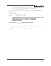
APPENDIX B. SETUP CONFIGURATION
In order to configure the MIUXXX/485 to remote RTU, Meter or Scada terminals the
following setup is required for 2w or 4w (RS485) networks
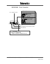
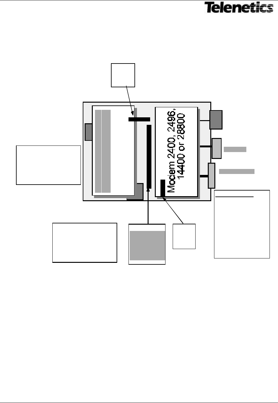
See Fig ONE for MIUXXXX/485 layout and dip switch setting
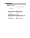
Final Factory Configuration (MIUXXXX/485) for PEXXX modem module
No, Power saving modes, No Auto Reset mode
Switch two ON Switch one, three and four are OFF.
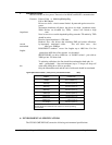
MIU S3 (external)
SW-2 Closed (ON) MIU is configured for DB9 interface to
Modem interface connection.
SW-1, -3 & -4 Open (OFF)
Switch Three Setting
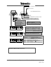
SW - One On
SW - Two Off
SW - Three Off
SW - Four Off
Switch
Three
DB9 (RS232)
Configuration
only
RJ11
Telco
Power
Plug
Switch
One
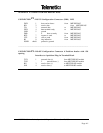
J2 Pin1
Jumper
3 & 4
5 & 6
7 & 8
13 & 15
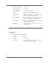
Switch One Setting
SW - One Off
SW - Two On
SW - Three Off
SW - Four Off
DB 9 Connection
1 Carrier Detect
2 Received Data
3 Transmit Data
4 DTR
5 Signal Ground
6 DSR
7 RTS
8 CTS
9 Ring Indicator
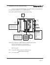
Jumper 7
Pin 1
3&4
J 8
Pin 1
2 & 3
RS485 Module