Install Op and Diags for MIU Modems and RS485 (0049-0002-010A) Page 2 of 16
3. MIU'S LED, SWITCH & SERIAL CONNECTOR SPECIFICATIONS
The CIU/485 communicates with industrial controllers through RS-485 compatible serial
signaling. The RS-485 signal levels are used to interconnect with RS-485 compatible
embedded controllers. The RS-232E signal levels are used to configure the CIU. The RS-
232E signal levels are also used to interconnect with RS-232E compatible embedded
controllers if required.
The RS-232E is present on DB9(MIU), RS485 signal levels are available via four pins'
connectors.
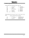
4.1 The following lists the CIU/485 serial interfaces. All connector definitions are
described in Appendix A
RS-232 Configuration Connector (P2)
Connector Type: DB9, (MIU) female, straight board mounts.
Signal Levels: RS-232
RS485 Configuration Connector (P1)
Connector Type: 4 pin terminal header with .138 spacing
Signal Levels: RS485
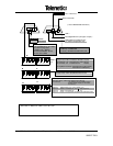
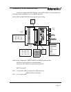
3.2 MIU/485 LED
LED Blinks every 4 seconds with AC / DC power
3.3 MIU/485 LED & Switch 1 (internal)
S1-1 Closed (ON) LED Blinks with option CD (&C1 AT command) active
S1-2 Closed (ON) LED Blinks AC. DC Power ON Note select either 1 or 2
S1-3 Closed, option modem DTR select DB9 DTR
S1-4 Closed, option modem DTR select modem's CD
3.4 MIU/485 Switch S3 (external)
S3-2 Closed (ON) only for MIU/485 (J1) modem configuration or for
RS232 embedded controllers.
S3-1,-3 &-4 Open (OFF)
S3-1 Closed (ON) only for MIU/485 (P1) RS485 connector (RS485
embedded controllers)
S3-2,-3 &m-4 Open (OFF)
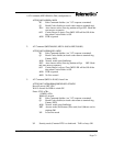
3.5 MIU/485 A switch (external)
SA-1 Closed (ON) RS485 received data disable TX (Driver Output Enable)
SA-2 Closed (ON) RS485 transmit data enable TX (Driver Output Enable) + 5ms
SA-3 Closed (ON) RS485 RTS enable TX (Driver Output Enable) should be
Open (OFF)
SA-4 Closed (ON) RS485 received data is disables with TXD


