


GE863-QUAD
GE863-PY
1vv0300715 Rev. 1 - 19/09/06
Reproduction forbidden without Telit Communications S.p.A. written authorization - All Right reserved page 61 of 79
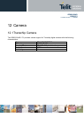
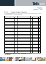
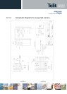
12.1.1 Camera Interface Connectors
The pinout of the module and a 24 pins ZIF connector for the CMOS camera provide the interface connection
between GE863-QUAD / PY and Transchip camera.
GE863-QUAD / PY signal
TC5747MF24L
Pin Signal I/O Notes Pin Signal I/O
55 GPIO3 O I2C bus serial clock 1 SCLK I
8-17… GND Ground 2 AGND I
31 VAUX O Power Supply 3 AVDD28
*
I
5 GPIO9 O Camera Reset 4 RESET_N I
7 MON1_CAM O Clock 5 CLK_IN
**
I
8-17… GND Ground 6 DGND I
n.c n.c. 7 DOUT_0 I/O
n.c n.c. 8 DOUT_1 I/O
n.c n.c. 9 DOUT_2 I/O
n.c n.c. 10 DOUT_3 I/O
n.c n.c. 11 DOUT_4 I/O
n.c n.c. 12 DOUT_5 I/O
n.c n.c. 13 DOUT_6 I/O
n.c n.c. 14 DOUT_7 I/O
n.c n.c. 15 DOUT_8 I/O
n.c n.c. 16 VCLKOUT O
n.c n.c. 17 VALIDH O
n.c n.c. 18 VALIDV O
31 VAUX O Power Supply 19 DVDD28 I
32 GPIO4 I/O
I2C bus serial data
20 SDIN I/O
8-17.. GND Ground 21 PS1 I
6 GPIO8 O Camera power type selector 22 PS2 I
8-17… GND Ground 23 SHIELD -
Flash Enable 24 LED_CTRL O
*
Filter the AVDD28.
**
Use a Buffer between module clk out, MON1_CAM and camera clk in, CLK_IN.
***
Non-connected.