


www.ti.com
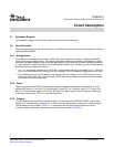
* dBFS + 20 log
captured max code * captured min code
2
N
, where N is the number of bits.
EVMOperationalProcedure
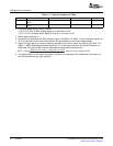
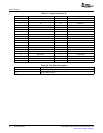
Table1-1.ThreePinJumperListTable
JUMPERFUNCTIONLOCATION:PINS1–2LOCATION:PINS2–3DEFAULT
SJP3ProvidesAIN+sourcetoADCSourceprovidedfromT2SourceprovidedfromDiffAmp1–2
device
SJP4ProvidesAIN–sourcetoADCSourceprovidedfromDiffAmpSourceprovidedfromT22-3
device
2.ConnectsuppliestotheEVMasfollows:
+5V(4.75V–5.25V)ADCanalogsupplytoJ3andreturntoJ2.
+3.3V(3V–3.6V)digitalbuffersupplytoJ4andJ1andreturntoJ6
3.Switchpowersupplieson.
4.Useafunctiongeneratorwith50-Ωoutputtoinputa105-MHz,0-Voffset,1-Vrmssine-wavesignalinto
J5.Thefrequencyoftheclockmustbewithinthespecificationforthedevicespeedgrade.
5.Supplyaninputsignalbyusingafrequencygeneratorwitha50-Ωoutputtoprovidea15.5MHz,0-V
offset,–1-dBFSamplitudesine-wavesignalintoJ11.Afull-scaleinputtoneintotheADCdeviceisa
differential2.2VppanddBFScanbecalculatedbyusingthefollowingformula:
6.ThedigitalpatternontheoutputconnectorJ9shouldnowrepresenta2'scomplimentsinewaveand
canbemonitoredusingalogicanalyzer.
6OverviewSLWU020B–February2005–RevisedFebruary2006
SubmitDocumentationFeedback