


www.ti.com
3.2.7LEDOperation
CircuitDescription
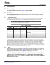
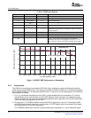
Table4.TestPoints
TPDESCRIPTION
TP1ADCcommonmode,inputoroutput
dependingonthesettingofSW1,switch4
TP3THS4509powerdown
TP4ADCoutputenable
TP5AGND
TP6AGND
TP7AGND
TP8DGND
TP9FPGAM0pin;determineswhichFPGAlogic
filetoload
TP10ADCSCLK
TP11TPS750031.2enable
TP12TPS750032.5enable
TP13TPS750033.3enable
TogivegreatervisibilityintotheEVMoperations,twoLEDsareprovided,D3andD4.Onpowerup,D4is
assertedwhenasuccessfulFPGAbootupiscomplete.ForcorrectEVMoperation,theLEDshouldbe
assertedatalltimes.LEDD3isassertedwhentheADCandFPGAareoperatinganddecodinginDDR
LVDSmode,andisnotassertedwhentheADCisfunctioninginCMOSmode.Furthermore,ineitherDDR
LVDSmodeorCMOSmode,LEDD3blinkswhenanADCoverrangeconditionoccurs.
CAUTION
IfLEDD3isblinking,theamplitudecomingintotheADCinput(J3orJ4)must
beattenuatedimmediately;otherwise,damagetotheADCcouldoccur.
12SLWU028B–January2006–RevisedNovember2006
SubmitDocumentationFeedback