


www.ti.com
3CircuitDescription
3.1SchematicDiagram
3.2CircuitFunction
3.2.1ConfigurationOptions
3.2.2Power
CircuitDescription
TheschematicdiagramfortheEVMisinSection5.3ofthisdocument.
Thefollowingparagraphsdescribethefunctionofindividualcircuits.Seethedatasheetforcomplete
deviceoperatingcharacteristics.
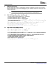
TheEVMprovidesaDIPswitch,SW1,tocontrolmanyofthemodesofoperationwhentheEVMis
configuredforparallel-modeoperation.Table1describesthefunctionalityoftheDIPswitches.
Note:Whenthedeviceisconfiguredforserial-modeoperation(SW1,switch8),theDIPsettings
onSW1,switch1throughSW1,switch7areignored.
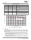
Table1.DIPSwitchSW1
SW1SWITCH
OFFONDESCRIPTION
NUMBER
12scomplementOffsetbinaryDeterminesdeviceoutputformat
2LVDSCMOSDeterminesdeviceoutputmode
3ReservedReservedReserved
4InternalreferenceExternalreferenceWhensettoExternalReference,ADCusescommon-mode
voltageonTP1.
5Edge=1Edge=2Allowsforoutputedgeprogrammability
6Edge=3Edge=4Allowsforoutputedgeprogrammability
7NormalPowerdownAllowsforpowerdown
8SerialParallelDeterminesmodeforregisterinterface
ByswitchingSW1,switch8toOFF,theADCoperatesinserialmode,usingitsprogrammedregister
contents.Acompleteregistermapcanbefoundinthedevicedatasheet.ThreepinsonheaderJ6have
beenreservedforprogrammingthedevicewhileitoperatesinserialmode.Toprogramthedevice
registersusingheaderJ6,placeSCLKonpin21,SDATAonpin23,andSENonpin25.Apattern
generatorcanbeusedtogeneratethepatternsneededforprogramming.Alternatively,TIprovidesan
optionalUSBdaughtercardthatplugsintotheexpansionslotoftheEVM.TheUSBdaughtercardallows
ADCregistercontrolviaasoftwarepackageloadedontothePC.
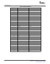
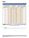
PowerissuppliedtotheEVMviabananajacksockets.TheEVMoffersthecapabilitytosupplyanalog
anddigital3.3VindependentlytotheADC.Table2offersasnapshotofthepower-supplyoptions.All
supplyconnectionsarerequiredfordefaultoperation,exceptJ12,J10,J13,andJ20.
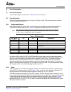
TheEVMprovideslocaldecouplingfortheADC;however,theADCfeaturesinternaldecoupling,andin
manycasesminimalexternaldecouplingcanbeusedwithoutlossinperformance.Usersareencouraged
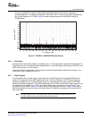
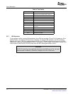
toexperimenttofindtheoptimalamountofexternaldecouplingrequiredfortheirapplication.Figure1
showstheADS5547LVDS-modeperformancewithallofthedecouplingcapacitorsinstalledandthe
performancewithC4,C5,C6,C7,C8,C9,andC10removed.Bydefault,theEVMcomeswithallofthe
decouplingcapacitorsinstalled.
SLWU028B–January2006–RevisedNovember20067
SubmitDocumentationFeedback