


CC2511 Dongle
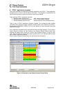
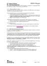
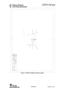
8 CC2511 Dongle hardware description
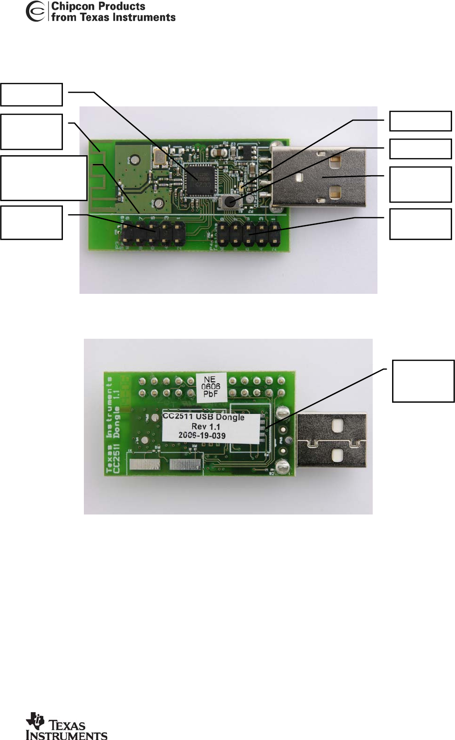
Debug
connector
Line marking
cutaway section
of the dongle
PCB
antenna
CC2511
USB
connector
Button
LED
GPIO
testpins
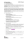
Figure 11: CC2511 Dongle top view
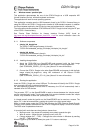
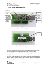
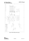
Alternative
debug
connector
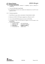
Figure 12: CC2511 Dongle back view
8.1 User Interface
The CC2511 Dongle has one button and one LED that can be used to interact with the user.
The LED is connected to pin P1_1. Setting P1_1 high (to logic 1) will turn the led on.
The button is connected to pin P1_2 and GND. The pin P1_2 should be configured as an
input with pull-up. The button is pushed when P1_2 is pulled low (to logic 0).
8.2 USB interface
The CC2511 Dongle has a standard USB connector. The dongle is powered through this
connector. On the D+ line there is a pull-up used to identify the dongle as a full-speed USB
unit on the USB bus. The pull-up can be controlled from the firmware, using P1_0. This
enables the firmware to be connected to the USB bus for a period of time before it signals its
presence to the USB hub.
SWRU082 Page 18 of 24