


CC2511 Dongle
5 Using SmartRF04EB as an In-Circuit Emulator (ICE)
The SmartRF04EB can be used as ICE for the CC2511
To use the SmartRF04EB as ICE, the IAR Embedded Workbench software must be installed.
The Embedded Workbench is a C-Compiler, Simulator, and ICE debugger. See the IAR
Embedded Workbench documentation supplied with the kit for instructions how to set up the
ICE debugger for use as an ICE.
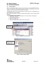
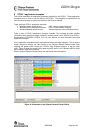
When the SmartRF04EB is connected to a PC with the USB port, the debugger will connect
to the SmartRF04EB. Several SmartRF04EB can be connected to USB ports simultaneously.
A selection window will display the connected SmartRF04EB, and the user can select which
device to load.
For custom PCB’s with the CC2511, it is recommended to include a pin header or test points
to allow in-circuit emulation or programming using SmartRF04EB or other 3rd party
programming tools. Use the CC2511 Dongle as a reference. Please see the
CC2510/CC2511section of the Chipcon web site for an updated list of 3rd party programming
tools.
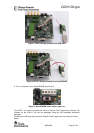
When using smartRF04EB as emulator for external target debugging any CCxxxxEM module
must be removed
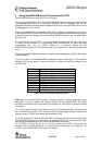
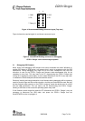
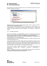
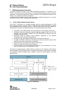
The pin-out used on the SmartRF04EB is explained in Table 1 and Figure 4. The connector
includes 4 SPI control signals. These are currently not used, but they are included to give
users flexibility.
Pin Function
1
Gnd
2
VDD
3 Debug Clock(DC)
4 Debug Data(DD)
5 CSn(optional)
6 SCLK(optional)
7 Reset_N
8 MOSI(optional)
9 3.3V VDD, alt. NC
10 MISO
Table 1: P14 SOC debug connector pin-out
VDD note: The SmartRF04EB includes a voltage converter to support programming and
debugging of external systems with different voltage than the SmartRF04EB. The debug
connector includes two VDD connections on pin 2 and pin 9. The function is different for these
connections.
Pin 2 VDD supplies voltage to the voltage converter. If the target application is self powered
pin 2 should be connected to VDD to assure that the correct supply voltage is used for the
voltage converter. This pin must always be connected to VDD.
Pin 9 VDD supplies 3.3V from the SmartRF04EB. If the target application is powered from the
SmartRF04EB supply during programming and debugging this pin can be connected to VDD.
If the target voltage differs from 3.3V, this pin should not be connected.
On the CC2511 Dongle this pin is not connected. Hence the CC2511 Dongle must be
powered from a separate USB cable or a separate cable connecting pin 9 on “test pins” / P4
to VDD on the SmartRF04EB. See chapter 4 for details.
SWRU082 Page 6 of 24