


2 Setup and Required Equipment
2-3
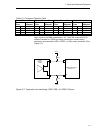
Table 2-1 Crosspoint Function Table
Output Channel 1 Output Channel 2 Output Channel 3 Output Channel 4
Control
Pins
Input
Selected
Control
Pins
Input
Selected
Control
Pins
Input
Selected
Control
Pins
Input
Selected
S10 S11 1Y/1Z S20 S21 2Y/2Z S30 S31 3Y/3Z S40 S41 4Y/4Z
0 0 1A/1B 0 0 1A/1B 0 0 1A/1B 0 0 1A/1B
0 1 2A/2B 0 1 2A/2B 0 1 2A/2B 0 1 2A/2B
1 0 3A/3B 1 0 3A/3B 1 0 3A/3B 1 0 3A/3B
1 1 4A/4B 1 1 4A/4B 1 1 4A/4B 1 1 4A/4B
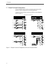
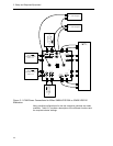
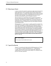
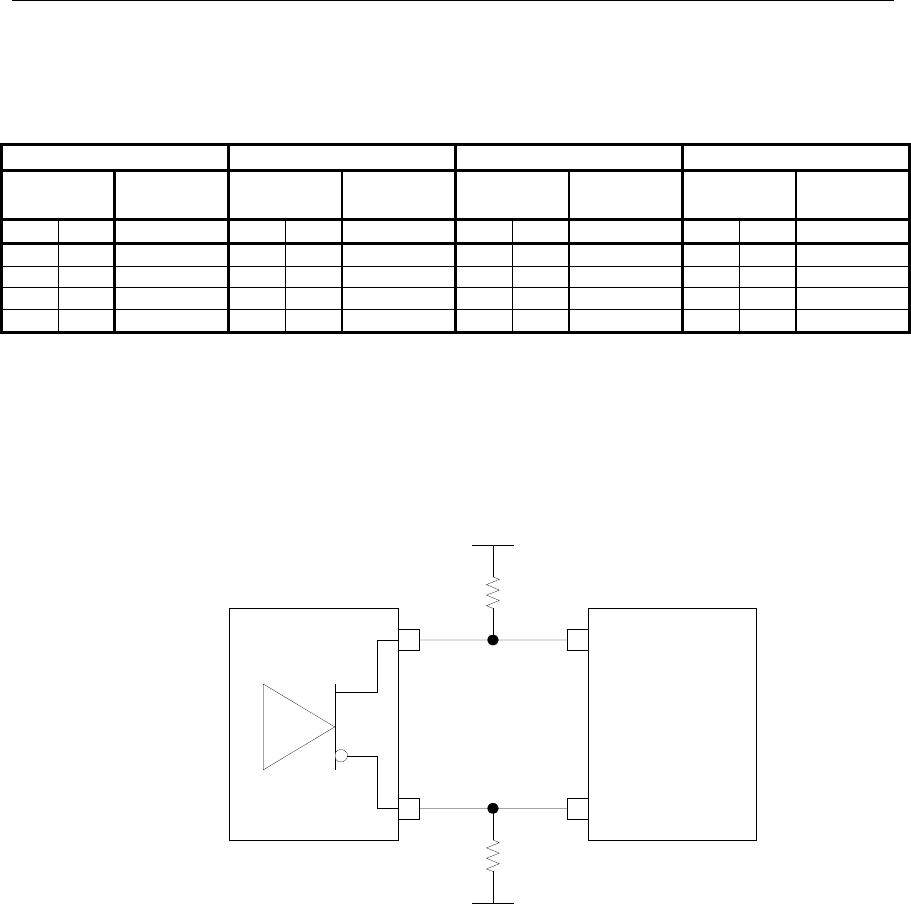
Apply inputs to the SMA connectors J1–J8. The EVM comes with 50-Ω
resistors installed to VTERM, providing a termination scheme easily
adjusted to accommodate LVDS, LVPECL, or CML output structures. (See
Figure 2-2).
LVDS,
LVPECL,
or CML
Vterm
Vterm
50 Ω
50 Ω
A
B
SN65LVDS125 Input
Channels 1-4
Figure 2-2. Termination for Interfacing LVDS, CML, or LVPECL Drivers