


ADC Power
4-2
4.1 ADC Power
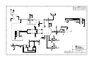
The device installed on the modular MSOP8 EVM has several options in
regards to its power source. Refer to the schematic for the following
discussion.
JMP1 and JMP3 allow the user to select the power supply used by the ADC.
When JMP1 is in the default factory position (Shunt on pins 1-2), power to the
ADC comes from J3.3 or TP5. Single gate digital buffers (U3, U5, and U6) are
installed on the ADC’s digital input/output lines to allow operation with low
voltage controllers, such as the MSP430. The supply voltage to these buffers
is determined by JMP3 or the voltage applied to TP7.
4.2 Stand Alone Operation
When used as a stand alone EVM, the analog power can be applied to TP5,
referenced to TP6. Digital power can be applied to TP7 referenced to TP4.
While filters are provided for all power supply inputs, optimal performance of
the EVM requires a clean, well-regulated power source.
Caution
The ADC’s that are compatible with this EVM have a variety of
power supply requirements. Check the appropriate data sheets
and verify all power supplies are within the safe operating limits of
the ADC before applying power to the EVM.
4.3 Reference Voltage
The modular MSOP8 can be configured to use the onboard reference/buffer
circuits (U2 and U4) or an external reference applied to J1.20. Jumpers JMP5
and JMP6 control the reference source. In the factory default position (shunt
on JMP5 pins 1-2), a 2.5 V reference is supplied by U2. Moving the shunt at
JMP5 to positions 2-3 allows an external reference applied to J1.20 to be
used.
Caution
The ADC’s that are compatible with this EVM have a variety of
reference requirements. Check the appropriate data sheets and
verify external reference sources are within the safe operating
limits of the ADC before applying power to the EVM.
JMP6 controls the actual application of the reference source to the ADC. Note
that JMP6 is not installed on EVM boards for ADS7818, ADS7834, and
ADS7835 devices. In the factory default position (shunt on pins 1-2), the
reference source is the on board reference/buffer circuit. Moving the shunt on
JMP6 to pins 2-3 allows the voltage applied to the ADC (+Vadc) to be used
as the reference source.