www.ti.com
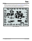
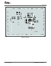
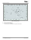
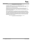
1.3PrintedCircuitBoardAssembly
1.4USBtoI
2
CInterfaceBoard(EV2300)
1.5Software
2Setup
2.1Input/OutputConnectorDescriptions
Setup
TheTPS65020EVM-110PCBcontainstheTPS65020ICanditsrequiredexternalcomponents.This
boardcontainsseveraljumpersandconnectorsthatallowtheusertocustomizetheboardforspecific
operatingconditions.
TheEV2300isthelinkthatallowsthePCandtheEVMtocommunicate.OneendoftheEV2300
connectstothePCwiththesuppliedUSBcable,andtheotherendoftheEV2300connectstotheEVM
withthesuppliedMolexcable.WhentheuserwritesacommandtotheEVM,theinterfaceprogram,which
isrunfromthePC,sendsthecommandtothePCUSBport.TheEV2300receivestheUSBcommand
andconvertsthesignaltoanI
2
Cprotocol.ItthensendstheI
2
CsignaltotheTPS65020board.Whenthe
userreadsastatusregisterfromtheEVM,thePCsendsacommandtoreadaregisterontheEVM.
WhentheEVMreceivesthecommand,itreportsthestatusoftheregisterviatheI
2
Cinterface.The
EV2300receivestheinformationontheI
2
Cinterface,convertsittoaUSBprotocol,andsendsittothe
PC.
TexasInstrumentshasprovidedsoftwaretoassisttheuserinevaluatingthisEVM.Toinstallthesoftware,
inserttheenclosedCDintoyourcomputer.Thesoftwareshouldstartautomatically.Ifitdoesnot,simply
goto<Start>,<Run>,andtype“D:\SLVU138.exe”,andclick<OK>(assumingthatD:isyourCDdrive).
Theprogramshouldrunwithouterrors.Ifanyproblemsoccurthatresultintheprogramnotbeing
installed,viewthereadme.txtfileontheCDforfurtherinformation.ChecktheTPS65020productfolderon
theTIwebsiteforthelatestrevisionofthesoftware.
ThissectiondescribesthejumpersandconnectorsontheEVMaswellashowtoproperlyconnect,setup,
andusetheTPS65020EVM-110.
INPUT/OUTPUTDESCRIPTION
Inputvoltagefromexternalpowersupply,recommendedmaximum5.5V.Inputcurrentisdependent
J1–VIN
onloadbutistypicallybelow2A.
J2–GNDThisisthereturnconnectionforV
I
.
InputvoltageandreturnforLDO1andLDO2C.ResistorR23connectsthispintoVDCDC1.Ifan
J3–VINLDO/GND
externalpowersupplyisused,removeR23.Recommendedmaximuminputvoltageis5.5V
InputvoltageandreturnforVSYSIN,oneoftheinputvoltagesforRTC.ResistorR24connectsthis
J4–VSYSIN/GNDinputtoVDCDC1.Ifanexternalpowersupplyisused,removeR24.Recommendedmaximuminput
voltageis4V
InputvoltageandreturnforVBACKUP,oneoftheinputvoltagesforRTC.Thereisnoonboard
J5–VBACKUP/GND
connectionstoavoltageinput.Recommendedmaximuminputvoltageis4V.
DirectconnectiontotheGPIO1andGPIO2pins.ForthisEVM,GPIO1isconfiguredasa
J6–GPIO1/GPIO2
push-buttoninput,andGPIO2isconfiguredasanLEDoutput.
J7–VRTC/GNDOutputvoltagefromtheRTCcircuit.
Fourfaultoutputsareavailableonthisconnector:
PWRFAIL-Faultoccurswheninputvoltageisbelow3V.PulleduptoVRTCwhensafe,lowforfail.
INT-Faultoccurswhenthereisafailonaninputoroutputvoltage.Itactsasasumfail.Pulledup
J8–FaultOutputs
toV
I
whensafe,lowforfail.
RESPWRON–LowresetsignalcontrolledbySW2,300mS.PulleduptoV
I
normally.
LOWBAT–Faultoccurswheninputvoltageisbelow3.6V.PulleduptoV
I
whensafe,lowforfail.
J9–USBThisheaderduplicatesthesignalsfromtheJ20interfaceconnector.
OutputfromDCDC1switchingregulator,maximumoutputcurrentis1.2A,defaultvoltagesettingis
J10–VDCDC1
3.3V.
TPS65020EVM-110User'sGuide 2SLVU138–August2005


