


www.ti.com
2.2RXOperation
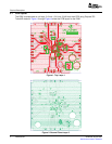
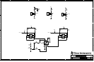
3PhysicalDescription
PhysicalDescription
1.SetTR(J13)tologic0.
2.SetPA_ASEL(J10)tologic0.
3.ConnectadifferentialLOsourcetotheLOP/LONSMAs(oruseanexternalbalun).
SettheLOtoanappropriatefrequency,withthepowerlevelbetween0to+4dBm.Rememberthatfor
A-bandoperation,theLOinputfrequencyisdoubledinsidetheTRF2436;so,theLOshouldbesetto
halfthefrequencydesiredatthemixerLOport.
4.Formixerstagemeasurement:
a.TerminateRFA(J9)andRFANTA(J6)into50Ω.
b.ConnectanRFsourcetoMFA(J8).SettoadesiredRFfrequencyandtypicalpowerlevel
of–20dBm.
c.ConnectaspectrumanalyzertotheIF(J7)output.
d.Turnonthe3.3-Vpowersupply(~90mA).
e.ObservetheIFoutputonaspectrumanalyzer(374MHz).
5.ForLNAstagemeasurement:
a.TerminateIF(J7)andMFA(J8)into50Ω.
b.ConnectanRFsourcetoRFANTA(J6).Settoadesiredfrequencyandtypicalpower
levelof–40dBm.
c.ConnectaspectrumanalyzertoRFA(J9).
d.Turnonthepowersupply.
e.ObservetheLNAoutputonaspectrumanalyzer.
f.UsejumperJ14(RXDGC)toselectbetweenLNAhigh(pins2-3)andlowgain(pins1-2)
modes.
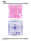
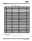
ThissectiondescribesthephysicalcharacteristicsandPCBlayoutoftheEVMandliststhecomponents
usedonthemodule.
SLWU038–August2006TRF2436EVM3
SubmitDocumentationFeedback