


Running Title—Attribute Reference
2-2
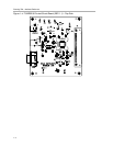
2.1 TUSB3210 Setup
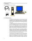
The TUSB3210 EVM supports many USB applications. The jumpers allow the
flexibility to configure the EVM in various modes for evaluation purposes. Note
that some modes require additional components not included with the EVM kit.
The EVM comes in a default configuration that requires no additional
components on the EVM. A full description of the TUSB3210 device is
specified in the data manual (SLLS466). The PC must be running a
USB-capable operating system.
If necessary, configure the EVM based on the desired settings specified later
in this section. Use a standard USB cable to connect the TUSB3210 EVM to
a downstream port on the PC or to a USB HUB tier.
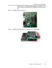
2.2 Interfaces and USB Port
The EVM uses a standard type-B connector for the upstream port. An I
2
C
serial interface is provided to access an I
2
C EEPROM. A UART port is
embedded in the microcontroller and is connected to the RS-232 port on the
EVM. The RS-232 port connection can be broken using the jumpers. See
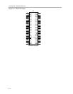
jumper settings for more details. All GPIO signals are available on the 50-pin
connector JP1 for use by the specific application.
2.3 Power Supplies
The TUSB3210 EVM requires a single positive 5-V power supply for operation.
Two options are available for supplying power to the EVM:
- Self-powered mode: a switching 5-V dc power supply plugged into (J1)
- Bus-powered mode: 5-V power is supplied by the USB cable.
Note that the supply needs to have a rating of at least 0.5 A. The EVM may fail
to operate properly with less power. An onboard low-dropout regulator is used
to generate a 3.3-V supply from the 5-V external supply. The red LED (D4) is
on when the platform is powered. See also the Jumpers and Switches section.
2.4 Light Emitting Diodes (LEDs)
Table 2−1. LED Description
LED LED Description
D4 Red LED on indicates that the EVM is powered on and not suspended.
Red LED off indicates that the EVM is powered off or suspended.