


Running Title—Attribute Reference
2-3
Chapter Title—Attribute Reference
2.5 Jumpers and Switches
Table 2−2 is provided to help set up and configure the EVM platform jumpers
to the desired mode of operation. The EVM can download firmware code from
the PC through a loading program (which may or may not be supplied with your
EVM) or from an I
2
C EEPROM. A 5-V power source may be supplied from an
external source or from the USB cable. If supplied from an external source, U2
must be set to position 2−3. If supplied from the USB cable, set U2 to position
1−2. The 5-V source is used to generate 3.3 V using an LDO regulator. JP2
and JP3 are used to connect P3.0 and P3.1 to R1OUT and T1IN of the RS232
connector, respectively. JP4 must be set to off when not using the MCU’s
UART.
Table 2−2. Jumpers and Switches
Jumper/Switch Jumper/Switch Description
U2 Position 1−2: 5-V bus power supply; position 2−3: 5-V dc or 5-V switching supply
JP2 Position 1−2 on: connect P3.0 to R1OUT; position 1−2 off: disconnect P3.0 from R1OUT
JP3 Position 1−2 on: connect P3.1 to T1IN; position 1−2 off: disconnect P3.1 from T1IN
JP4 Position 1−2 on: supplies power to RS−232 transceiver; position 1−2 off: RS−232
transceiver is not powered. See Note.
NOTE: JP4 supplies 5 V to the RS−232 transceiver for the REV 1.1 board. JP4 supplies 3.3 V to the RS−232 transceiver for the
REV 1.2 board.
2.6 EEPROM
The I
2
C EEPROM provides application-specific firmware. The TUSB3210
automatically reads the EEPROM at power up via the I
2
C bus. A header must
be added to the application firmware before loading into the EEPROM. See
the TUSB2136/3210 Bootcode Document for USB to General_Purpose
Device ccontroller user’s guide (SLLU025) for a description of the header
definition. The header may be generated automatically using the I
2
C Header
Generation Utility software provided with the device.
The EVM ships with a preprogrammed EEPROM that has either keyboard
controller firmware or compact flash reader firmware. It enumerates properly
when connected to a USB host.
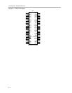
2.7 GPIO Connector
The 50-pin GPIO connector provides access to the TUSB3210 GPIOs as well
as some other control signals. Figure 2−1 shows the signals available on the
connector.