


3
6
7
13
8
9
10
11
14
15
16
18
17
19
12
12
20
3
5
5
4
21
24
23
25
26
22
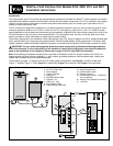
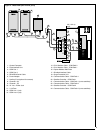
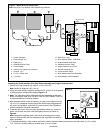
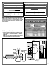
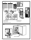
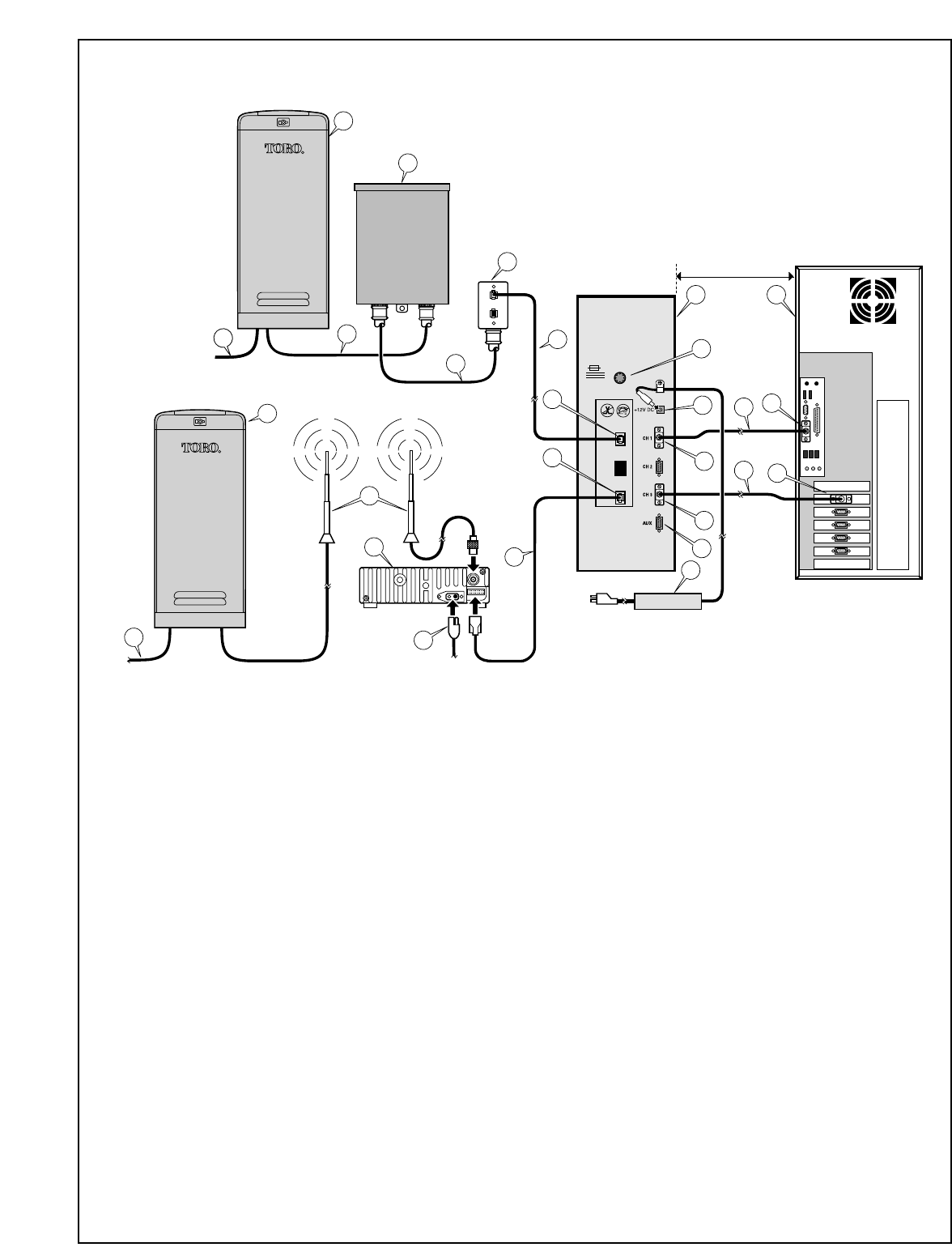
1 - Central Computer
2 - Field Interface Unit
3 - COM Port 1
4 - COM Port 2
5 - DB-9/DB-9 Serial Cable
6 - Power Adapter
7 - Auxiliary Port (optional for sensors)
8 - Channel 3 (in)
9 - Channel 1 (in)
10 - 12 V d.c. Power Jack
11 - 1.5A Fuse
12 - COM Line 1
13 - RJ11 Modular Cable
14 - Duplex Modular Wall Plate
15 - Shielded Interface Cable - COM Path 1
16 - Surge Protection Unit
17 - Communication Cable - COM Path 1
18 - Satellite Controller - COM Path 1
19 - Communication Cable - COM Path 1 (out to satellites)
20 - COM Line 3 (out)
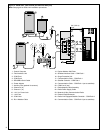
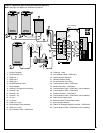
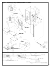
21 - Radio Adapter Cable Assembly
22 - Radio Power Supply Cable
23 - Motorola 2-Way Communication Radio
24 - External Radio Antennas
25 - Radio-Link Equipped Satellite Controller - COM Path 3
26 - Communication Cable - COM Path 3 (out to satellites)
Figure 3 - Model 2011 (one wireline port and one radio port)
Note: See page 9 for Radio-Link installation procedures.
50' (15.2 m)
max.