


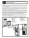
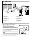

Processor Ready: Indicator light will illuminate when the microprocessor in the FIU has received configuration instructions
from PC and is ready to communicate with satellites or DIUs.
Field Transmit: Indicator light will illuminate or flash during transmission of data to field satellites or DIU(s).
Field Receive/Busy: Indicator light will illuminate or flash when receiving data from field satellites or detection of a busy chan-
nel by the radio.
Sensors (1–4): (Pending availability of SitePro sensor capability.) Sensor contacts are connected to a 12 V d.c. source within
the FIU and will be Normally Open operation type. Upon sensor activation, the contacts will close or connect, the light will illu-
minate and the FIU will signal the PC accordingly.
Note: An example of FIU sensor application is a rain switch. Purchase of sensors is optional (Sensor kit, Toro P/N 102-0397).
These sensors do not apply to sensors connected to field satellites.
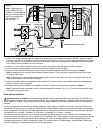
Satellite System Setup
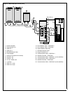
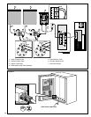
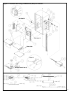
1. Check all cable connections at the Field Interface Unit, PC, Modular Wall Plate and SPU.
2. Switch on the Field Interface Unit.
3. From the SitePro program menu bar, select: Setup> Hardware.
4. From the “System” tab, select the applicable satellite hardware type.
5. From the “Communications” tab, select the “Wire” subtab.
6. Using the scroll down list provided, select the computer Com port associated with the FIU COM Port [L1] and/or [L2].
7. To establish a radio communication path, click on the “Radio” subtab and select the computer COM port associated with
this FIU connection.
8. Click OK to exit the setup window. This completes the setup procedure.
9. If the FIU is not active, restart SitePro with FIU COM Port Defined.
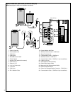
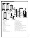
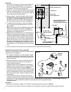
Radio-Link Installation (Models 2011 and 2021 only)
Note: The required Motorola
®
two-way communications radio, power supply and antenna components are not supplied.
CAUTION: Only the following 2-way radio and power supply models have been tested and approved for use with
the Radio-Link system. Radios and/or power supplies other than the following are subject to damage if installed. Per
FCC, Narrow Band is preferred over Wide Band.
Note:
Per FCC recommendations, Narrow Band is preferred over Wide Band.
•Motorola M1225, model number M44DGC90J2-A (Narrow Band). Maximum output - 25W.
•Motorola Radius SM50, model number M34DGC00A2AA (Narrow Band). Maximum output - 10W.
•Motorola MAXTRAC 300, model number D34MJA77A3CK (Wide Band), Maximum output - 1W.
•Motorola power supply models HPN4001 or HPN4002
CAUTION: Base station and satellite radio output wattage must not exceed the limit specified by the applicable
license. Special licensing and frequencies may be required for high wattage output.
CAUTION: High wattage output of the satellite radio can impair satellite operation. Ensure adequate spacing is
provided between the antenna and satellite to prevent the timing mechanism from malfunctioning due to induced RF.
The installation requirements listed below are essential for proper operation of the Radio-Link control system. If you have
any questions regarding the requirements and/or radio setup procedures, please contact a Toro distributor for assistance.
The following services and procedures must be provided by an authorized Toro representative or Motorola vendor:
•An installation site survey to analyze the location for the best radio frequency.
•Procurement of the radio frequency license.
•Selection of the required antenna type, size and height based on the distance and terrain between the central and satellite
controllers.
•The antenna cable type, length and installation method required for proper radio operation.
•Specific antenna requirements (height, power, location and lightning protection) to meet product safety and FCC regulations.
•Procurement of the required radio and power supply.
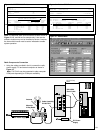
•The radio must be configured for Radio-Link operation as follows:
• Inputs and outputs set with Motorola radio service software similar to the example shown in Figure 12 for the MAXTRAC
300 radio, Figure 13 for the SM50 radio, or Figure 14 for the M1225 radio.
• Tx and Rx squelch type must be set to CSQ (open squelch).
9