


Chapter 1 Before Turning on the Power
Computer module C2PU37 User’s Manual
2
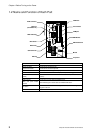
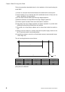
1.2 Name and Function of Each Part
PC card slots
INZ Switch
USB connector
DIP-SW
RST Switch
LEDs indicating
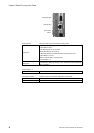
Mouse
Keyboard
RGB connector
COM por t
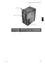
HDD Pack
Ethernet
(10/100base-TX)
HDD fixed board
HDD Drawer
10/100BASE-TX connector Connector for the Ethernet 10BASE-T/100BASE-TX connector.
Mouse connector Connector for the PS/2 mouse.
Keyboard connector Connector for the PS/2 keyboard.
RGB connector Connector for the analog RGB display
FDD connector Connector to connect the 3.5-inch (2HD, 2DD) external floppy disk drive.
RS-232C connector
(COM1)
Connector to connect the RS-232C interface device (such as mouse or
modem).
USB connector Connector to connect USB compatible device.
LEDs and push button
switches
LEDs indicating the module status and RESET/INZ button.
DIP switch
User settable switches. The setting can be read from user application
program in the C2.
PC card slots Slot to insert the PC card.