


31
4300 Series Ancillary Cabinets Installation and Operation Manual
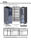
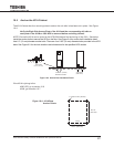
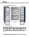
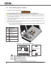
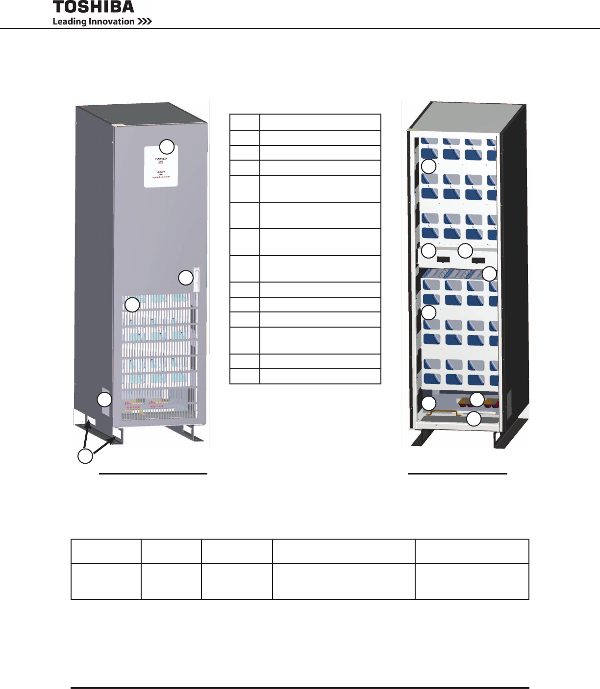
11 431B - Toshiba Battery Cabinet
No. Part
1 Toshiba Label
2 Door Latch
3 Ventilation Grill
4 Upper Battery Retention
Plate
5 MCCB1 - Upper Battery
Section Breaker
6 MCCB2 - Lower Battery
Section Breaker
7 Lower Battery Retention
Plate
8 Batteries
9 Power Bus Stubs (+), (-)
10 Ground Bus
11 Bottom Cable Access
Port
12 Side Cable Access Port
13 Forklift Fork Slots
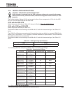
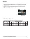
11.1 431B Estimated Runtimes
(All cabinets are O’Brien Black (Textured))
Xfmr Cabinet
Part Number*
UPS Rating DC Bus Nomi-
nal Voltage
Batteries/Circuit Breaker
Conguration
Battery Runtime in Min.
@ Full Load, 0.8 PF
431B- 300 – 30 kVA
300 – 30 kVA
500 – 50 kVA
R – 288 VDC 1- 1 Breaker, 3 Battery Strings
2- 2 Breaker, 6 Battery Strings
2- 2 Breaker, 6 Battery Strings
006 – 6 min. runtime
017 – 17 min. runtime
008 – 8 min. runtime
Example: 431B-500R2008 is a battery cabinet with upper and lower battery sections, nominal 288 DCV,
dual breakers sized for a 50kVA UPS with an approximate runtime of 8 minutes at 50kVA load at 0.8
Power Factor.
431B - Door Closed
3
2
13
1
12
431B - Door Open
4
7
5
8
10
11
9
6
Figure 11-1 - 431B Component
Identication