


40
4300 Series Ancillary Cabinets Installation and Operation Manual
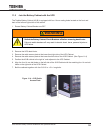
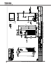
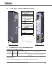
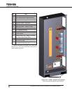
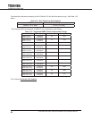
No. Part
5 Top Cable Access Plate
6 Side Cable Access Plate (removed)
7 Bottom Cable Access Plate
9A MBS Bus Stubs - Utility Input
9B MBS Bus Stubs - UPS Input
9C MBS Bus Stubs - UPS Output
9D MBS Bus Stubs - Output to Load
11 CB1 (UPS Input Isolation Breaker)
12 CB2 (Bypass Breaker)
13 CB3 (UPS Output Isolation Breaker)
14 Forklift Access
15
1
Cable Anchor Tray - Cable Tie Points
for Power Cable Strain Relief
16 Neutral Bus Strip
17 Ground Bus Strip
18 TB1 - (24Vdc Solenoid Lock Release
for Interlock Plate (Fig. 10))
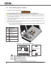
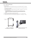
1 - Secure the cables with cable ties to the Cable
Anchor Tray. This will provide strain relief for the
upper power bus strips.
Figure 12-2 - 431M - Internal Arrangement
(Left Side Panel and Dead Fronts Removed)
7
6
15
12
5
13
11
14
16
17
9A
9C
9D
9B
18