


1. OUTLINE EO10-33013B
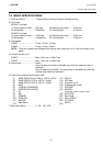
1.5 ELECTRONICS SPECIFICATIONS
1-10
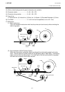
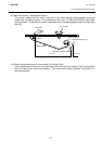
(3) Expansion I/O interface (B-SX4T: Option)
Interface circuit
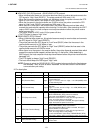
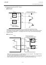
Input circuit
There are six input circuits, and each input is a current loop using a photo-coupler.
The anode of the photo-coupler is connected to common pin COM1 in each of the six circuits.
Each cathode is independent. The voltage of Vcc is 24 V (max.) while the diode operating
current is 16 mA.
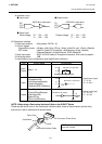
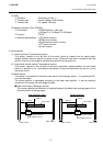
Output circuit
There are seven output circuits, and each output is an open collector. The voltage of Vcc is
24V (max.) while the operating current is 150 mA.
For other details, please refer to the Expansion I/O specifications stored in the enclosed CD-
ROM or posted on the web site with the URL, http://barcode.toshibatec.co.jp.
External controller, etc.
Vcc
R
R
Photo-coupler
TPL521 (TOSHIBA)
COM1
IN0
IN5
~
Printer
TLP521 (TOSHIBA)
External controller, etc.
(In the case of photo-coupler)
~
~
Printer
OUT0
OUT6
Vcc
COM2