


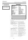
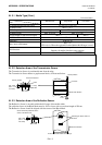

APPENDIX 1 SPECIFICATIONS
ENGLISH VERSION
APPENDIX2 INTERFACE
EA2-1
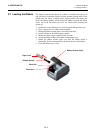
Function
9 pin
25 pin
RXD
2
3
TXD
3
2
DTR
4
20
GND
5
7
DSR
6
6
RTS
7
4
C TS
8
5
APPENDIX 2 INTERFACE
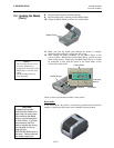
Interface Cables
To prevent radiation and reception of electrical noise, the interface cables must meet the following
requirements:
• Fully shielded and fitted with metal or metallized connector housings.
• Keep as short as possible.
•
Should not be bundled tightly with power cords.
• Should not be tied to power line conduits.
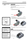
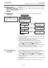
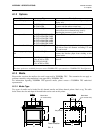
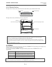
RS-232C Cable description
The serial data cable used to connect the printer to a host computer should be one of the following two
types (9-pin or 25-pin connector):
Connector to the Host Computer Connector to Printer
NOTE:
Use an RS-232C cable with a connector with inch type securing screws.
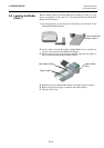
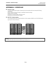
Pin No.
Function
1
+5V
2
TXD
3
RXD
4
RTS
5
GND
6
CTS
7
RTS
8
CTS
9
+5V