


E6581339⑥
10
3. Functional description
In this section, functions added by the installation of this expansion IO card option, on
top of the standard inverter functions, are described.
* If the software version of inverter is less than V104, when OUT3 or OUT4 terminals is
set as negative logic, it may output a flash pulse at inverter reset.
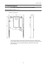
3.1 Multi-function output terminal
Two output terminals and one relay output can be added. Function is similar to that of the
output terminals of the inverter, so refer to the inverter instruction manual.
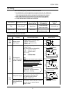
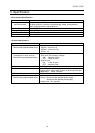
Parameter
Title Function Adjustment range Default setting
f133
Output terminal function selection 4 (OUT3) 0 - 255
254
(Always OFF)
f134
Output terminal function selection 5 (OUT4) 0 - 255
254
(Always OFF)
f135
Output terminal function selection 6 (R1) 0 - 255
254
(Always OFF)
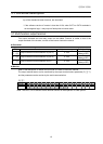
Monitor
Refer to the description on status monitor mode of inverter’s instruction manual.
The output terminal status can be monitored by the output terminal status parameter (fe07),
and the parameter can be monitor by the serial communication.
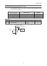
fe07
bit No. 15 14 13 12 11 10 9 8 7 6 5 4 3 2 1 0
Symbol
--- --- --- --- --- --- ---
R2
OUT
6
OUT
5
R1
OUT
4
OUT
3
FL
OUT
2
OUT
1
Note: The OUT5, OUT6 and R2 are the terminal function of the expansion IO card option 2.