


E6581339⑥
8
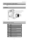
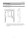
2.2 Wiring
When conducting wiring, follow the instructions below.
• Use shield wire for control signal line and ground the unit with shield wire
(Use twisted pair shield cable for wiring of the analog monitor output.
)
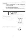
• Never bind the signal line and main circuit connection wire together
.
• Fix the communication cables after connected.
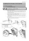
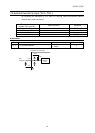
Terminal Block Applicable wire size
The wire length of
peel off the end
Using screwdriver
(The blade tip)
Tightening
torque
TB1 0.2 to 2.5 mm
2
About 7mm
0.6mm thickness
and 3.5mm width.
0.5 to 0.6 N・m
TB2 and TB3 0.2 to 1.5mm
2
About 5mm
0.4mm thickness
and 2.5mm width.
0.22 to 0.25 N・m
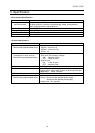
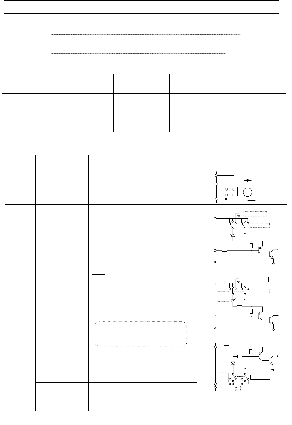
< Input/output terminal interface >
Terminal
symbol
Function Electrical specification Internal circuit
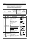
R1A
R1B
R1C
Relay contact
point output
Configuration of 1C contact point
250Vac - 2A (cosφ=1)
250Vac - 1A (cosφ=0.4)
30Vdc - 1A
R1A
R1B
R1C
Ry
LI1
LI2
LI3
LI4
Contact point
input Changeover
of sink or source
No voltage contact input
24Vdc - 5mA
Sink input (common voltage 24V)
ON :less than 10Vdc
OFF :16Vdc or more
Source input
ON :11Vdc or more
OFF :less than 5Vdc
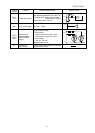
Note:
Even when an external power supply is
used (in sink logic mode i.e. when
SINK(PLC) is selected), connect
the reference potential-side (0V side)
cable from the power supply
to the CC terminal.
24V power supply
24Vdc power output (when SW1 is
in any position other than PLC)
24V internal output terminal
24Vdc - 60mA max
PLC/
P24
Common terminal
for external power
supply
If SW1 is turned to the PLC position,
this terminal can be used as a common
terminal when an external power
supply is used.
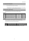
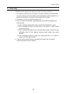
SINK Logic(SW=SINK(INT))
SW
2.2k ohm
2.2k ohm
CC
LI1
LI2
LI3
LI4
SOURCE
P24/
PLC
SINK(PLC)
SINK
(INT)
P24
SINK Logic (SW=SINK(PLC))
SW
2.2k ohm
2.2k ohm
CC
LI1
LI2
LI3
LI4
SOURCE
P24/
PLC
SINK(PLC)
SINK
(INT)
P24
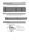
SOURCE Logic (SW=SOURCE)
SW
SOURCE
2.2k ohm
P24/
PLC
2.2k ohm
CC
LI1
LI2
LI3
LI4
SINK(PLC)
SINK
(INT)
P24
Lan current signal.
Chose low current contacts to
avoid poor attaching.