


E6581341
11
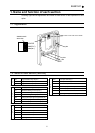
3.2. Multi-function input terminal
Four output terminals can be added. Function is similar to that of the input terminals of
the inverter, so refer to the inverter instruction manual.
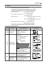
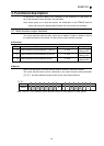
Parameter
Title Function Adjustment range Default setting
f123
Input terminal selection 13 (LI5) 0 - 135 0
f124
Input terminal selection 14 (LI6) 0 - 135 0
f125
Input terminal selection 15 (LI5) 0 - 135 0
f126
Input terminal selection 16 (LI5) 0 - 135 0
f145
*
Input terminal 13 - 20 response time selection 5 - 200ms 8
* VF-PS1 does not have this parameter.
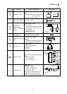
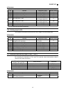
Monitor
Refer to the description on status monitor mode of inverter’s instruction manual.
The input terminal status can be monitored by the input terminal status parameter
(fe06), and the parameter can be monitor by the serial communication.
fe06
bit No. 15 14 13 12 11 10 9 8 7 6 5 4 3 2 1 0
Symbol
LI8 LI7 LI6 LI5 LI4 LI3 LI2 LI1 S4 S3 S2 S1
RES
ST R F
Note: The LI1 ~ LI4 are the terminal function of the expansion IO card option 1.
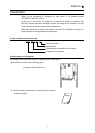
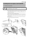
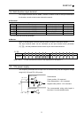
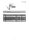
3.3. -10V power supply
The frequency command can be input from RX terminal with pulse and negative voltage
using N10(-10V) and PP(+10V) power.
Potentiometer
Center position: 0V command
Pulse side position: +10V command
Negative side position: -10V command
The recommended wiring cable length is
less than 1.5m with shielded cable.
Option Terminal
PP(+10)
RX
N10 -10V
2kΩ
Inverter Terminal