


2120
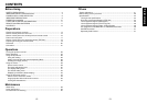
Preparations
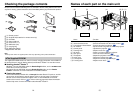
MONITOR
COMPUTER 2 IN
Y/P
B
/P
R
(
)
AUDIO OUT
AUDIO IN
CONTROL
S-VIDEO
VIDEO
COMPUTER 1 IN
Y/P
B
/P
R
(
)
R
L
p.47
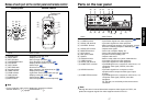
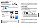
Before connection
• Read the owner’s manual of the device you are connecting to the projector.
• Some types of computer cannot be used or connected to this projector.
Check for an RGB output terminal, supported signal
p.45
, etc.
•Turn off the power of both devices before connecting.
• The figure below is a sample connection. This does not mean that all of these devices
can or must be connected simultaneously. (Dotted lines mean items can be exchanged.)
Notes
• COMPUTER terminals 1 and 2 function identically.
• For TDP-S21, the document camera should be connected to COMPUTER terminal 2.
• The AUDIO IN terminal doubles for devices connected to COMPUTER terminals 1 and 2.
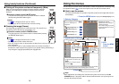
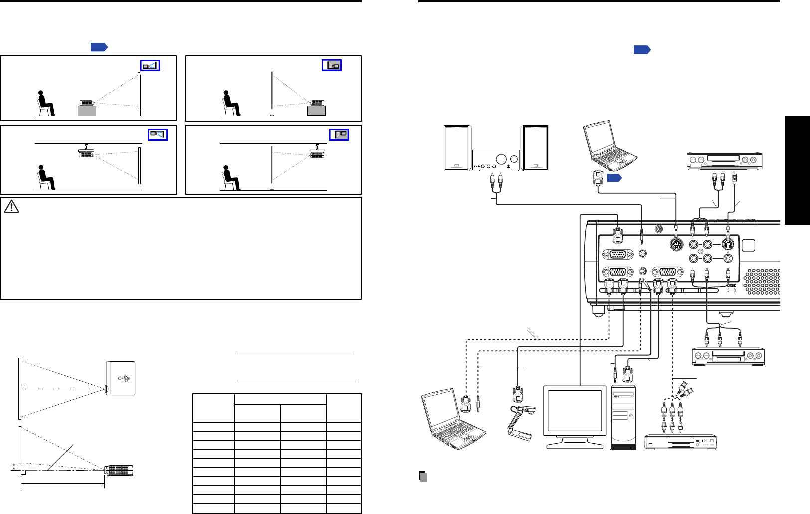
Connection
To audio
output
To RGB
output
Control cable
To RS-232C terminal
RGB cable
(not supplied)
To Y/CB/CR output
Green (Y)/Blue (C
B)/Red (CR)
VCR
S-Video cable
(not supplied)
Video cable
(not supplied)
To S-Video
output
To audio output
White (L)/Red (R)
Computer
(for control)
Conversion adapter BNC-pin
(not supplied)
Monitor cable Mini D-sub
15P-BNC
(not supplied)
Audio cable
(not supplied)
Video recorder,
DVD player, etc.
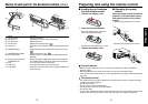
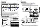
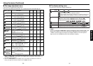
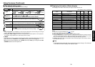
Projection Distance and Size
Use the figures, tables, and formulas below to determine the projection size and projection distance.
(Projection sizes are approximate values for full-size picture with no keystone adjustment.)
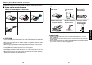
Placement Styles
As shown in the figures below, this device can be placed in 4 different styles.
The factory setting is “floor-mounted front projection.” Set the Projection mode in the
default setting menu
p.32
, in accordance with your needs.
Placement
Floor-mounted front projection
WARNING
• Always obey the instructions listed in IMPORTANT SAFETY INSTRUCTIONS when placing the unit.
Attempting to clean/replace the lamp at a high site by yourself may cause you to drop down, thus
resulting in injury.
• If you wish to mount the projector on the ceiling, be sure to ask your dealer to do so. Mounting the
projector on a ceiling requires special ceiling brackets (sold separately) and specialized knowledge.
Improper mounting could cause the projector to fall, resulting in an accident.
• If the projector is ceiling-mounted, install the breaker for turning off the power in case of anomaly. Let
everyone involved with the use of the projector know that fact.
Floor-mounted rear projection
Ceiling-mounted front projection Ceiling-mounted rear projection
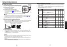
a
H
90
°
a is the distance (m) between the lens and the
screen, and corresponds to a range of 1.15 m to
10.00 m. H is the height from the image bottom to the
center of the lens.
Screen
As seen from above
Lens center
As seen from the side
a (min length) =
projection size (inches) – 1.516
29.85
a (max length) =
projection size (inches) – 1.264
24.88
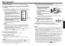
Audio amplifier, etc.
To audio
output
White (L)/
Red (R)
DVD video recorder, etc.ComputerComputer
RGB cable
(supplied with
TDP-S21)
Audio cable
(not supplied)
RGB cable
(supplied)
To RGB
output
Audio cable
(not supplied)
To audio input
White (L)/Red (R)
AV cable
(not supplied)
To audio
output
To video
output
Document camera
90
°
projection
projection distance a (m)
height (H)
min length max length
size (inches)
(zooming max) (zooming min)
(cm)
30 — 1.15 5.5
36 1.15 1.40 6.6
40 1.29 1.56 7.3
60 1.96 2.36 11.0
80 2.63 3.17 14.6
100 3.30 3.97 18.3
150 4.97 5.98 27.4
200 6.65 7.99 36.6
250 8.32 10.00 45.7
300 10.00 — 54.9