


1716
Preparations
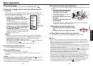
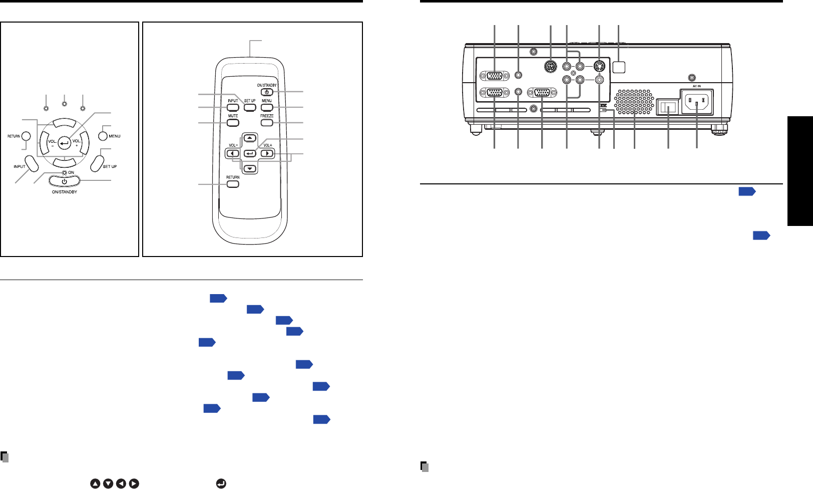
Note
• Although this owner’s manual abbreviates component video signals as Y/PB/PR, the
product also supports signals from video equipment marked “Y/C
B/CR.”
MONITOR
COMPUTER 2 IN
Y/P
B
/P
R
(
)
AUDIO OUT
AUDIO IN
CONTROL
S-VIDEO
VIDEO
COMPUTER 1 IN
Y/P
B
/P
R
(
)
R
L
(7)
(15) (13)(14) (12)
(4)
(5)(6)
(11)
(3)
(2)
(1)
(10)
(8)
(9)
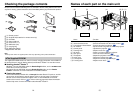
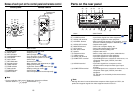
Name : Main Function
(1) Infrared remote sensor : Senses commands from the remote control.
p.19
(2) S-VIDEO terminal : Input S video signals from video equipment.
(3) AUDIO (L/R) terminal : Input audio signals from video equipment.
(4) CONTROL terminal : When operating the projector via a computer, connect
this to the controlling computer’s RS-232C port.
p.47
(5) AUDIO OUT terminal : Outputs audio signals.
(6) MONITOR terminal : Connect to a computer display, etc.
(7) AC IN socket : Connect the supplied power cord here.
(8) Main power switch : AC power line ON (standby)/OFF.
(9) Speaker : Outputs audio sound.
(
10
) Antitheft lock hole : Attach a safety cable or any other antitheft device.
(
11
) VIDEO terminal : Input video signals from video equipment.
(
12
) AUDIO (L/R) terminal : Input audio signals from video equipment.
(
13
) COMPUTER 1 terminal : Input RGB signal from a computer or other source, or a
component video signal (Y/P
B/PR) from video
equipment.
(
14
) AUDIO IN terminal : Input audio signals from a computer or video
equipment with a component video signal output
terminal.
(
15
) COMPUTER 2 terminal : Input RGB signal from a computer or other source, or a
component video signal (Y/P
B/PR) from video
equipment.
For TDP-S21, use exclusively for document camera
connection.
Parts on the rear panel
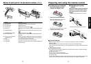
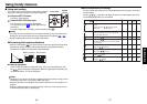
Names of each part on the control panel and remote control
Control panel Remote Control
(1)
(2)
(3)
(4)
(5)
(6)
(7)
(8)
(9)
(10)
(11)
FANLAMP
TEMP
(4)
(2)
(6)
(12)
(1)
(8)
(7)
(13)
(3)
Remote control
transmitter
Name : Main Function
(1) ENTER button : Accepts the selected mode.
(2) MENU button : Displays menus.
p.29
(3) SET UP button : Sets up image and mode.
p.26
(4) ON/STANDBY button : Turns the power on/off (standby).
p.22
(5) ON indicator : Displays whether power is on or off.
p.22
(6) INPUT button : Selects input.
p.24
(7) RETURN button : Goes back one screen.
(8) Selection button : Menu selections and adjustments,etc.
p.30
(9) LAMP indicator : Displays lamp mode.
p.23
(
10
) TEMP indicator : Lights when internal temperature too high.
p.41
(
11
)FAN indicator : Displays cooling fan mode.
p.41
(
12
) FREEZE button : Pauses image.
p.28
(
13
) MUTE button : Cuts off the picture and sound temporarily.
p.28
Note
• For the remainder of this manual, buttons are referred to as follows:
Selection buttons ⇒
; ENTER button ⇒