


36 ASC25 Instruction Manual
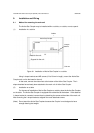
9.6 Procedure of design for laying optical fiber cables
For the use of TOSLINE-S20 optical fiber cable system, following-listed items shall be
observed to lay cables/codes.
(1) Precautions of optical fiber cable system design
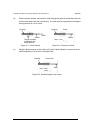
(A) Formulation of FC Type optical level diagram
• For FC Type, refer to the "T2/T3 stations instruction manual (6F3B0354)".
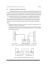
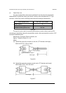
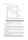
(B) Formulation of F07 Type optical fiber diagram
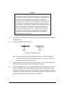
On designing an optical system, formulate the optical level diagram and confirm that the
light power has sufficient margin in advance. The following is an example of
transmission/receiving side level diagram. The example shows that the receiving side receives
up to -29 dBm of light power. Nevertheless, the receiving side is designed to be capable of min.
-25 dBm of light power taking into account of a margin. The level diagram given below does not
consider the presence of aligner at intermediate position.
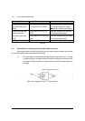
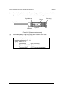
If an intermediate aligner exists, a corresponding light loss shall be added. Generally,
that kind of loss is 2 dBm with an aligner. However, calculation shall be done after inquiry to the
manufacturer, (use the worst case values.)