


Error! Style not defined. Error! Style not defined. 4 Replacement Procedures
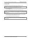
4.5 Top Cover
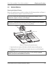
Removing the Top Cover
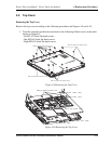
Remove the top cover according to the following procedures and Figures 4-9 and 4-10.
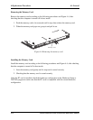
1. Turn the computer upside down and remove the following fifteen screws in the order
shown on figure4-9.
- Six M2.5x7 black flat head screws.
- One M2.5x4 black flat head screws.
- Eight M2x2.5 black flat head screws.
M2 5x7 black flat head screw.
M2x2 5 black flat head screw.
M2 5x4 black flat head screw.
M2 5x7 black flat head screw.
3
4
6
5
2
1
7
8
10
9
11
12
13
14
15
Figure 4-9 Removing the Top Cover
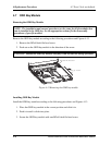
M2x3 0 black flat head screw.
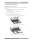
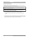
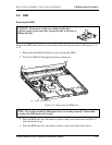
CN9
CN18
CN25
Power board cable
MMB board cable
Touch pad board cable
Bluetooth cable
Finger print cable
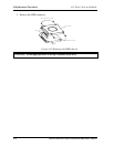
Figure 4-10 Removing the Top Cover
Satellite E100/E105/ Satellite ProE100/E105 Maintenance Manual 4-19