


4 Replacement Procedures 4.5 Top cover
4-20 Satellite E100/E105/ Satellite ProE100/E105 Maintenance Manual
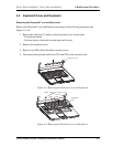
2. Restore the normal computer placement.
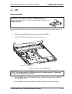
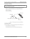
3. Disconnect the touch pad board flat cable from CN25, Finger print cable from CN51
MMB board flat cable from CN18, Power board flat cable from CN9 and Bluetooth
card cable from CN27.
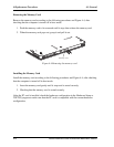
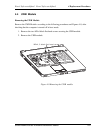
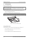
4. Remove the four M2x3 black flat head screw securing the top cover.
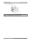
5. Lift up the top cover
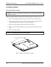
Installing the Top Cover
Install the top cover with the display assembly according to the following procedures and
Figures 4-9, 4-10.
1. Seat the top cover, adjusting its position.
2. Secure the top cover with four M2x3 black flat head screws.
3. Connect the touch pad board flat cable in to CN25, Finger print cable in to CN51
MMB board flat cable in to CN18, Power board flat cable in to CN9 and Bluetooth
card cable in to CN27.
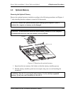
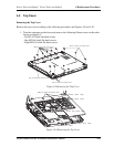
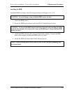
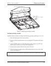
4. Turn the computer upside down and secure it with the fifteen screws in the order
shown on figure4-9.
- Six M2.5x7 black flat head screws.
- One M2.5x4 black flat head screws.
- Eight M2x2.5 black flat head screws.