


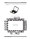
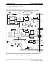

1 Hardware Overview 1.2 System Unit Block Diagram
1-10 TECRA S1 Maintenance Manual
•
EC
−
Power supply sequence control
−
Thermal control
−
LED control
−
Beep control
−
Device ON/OFF
−
Cooling fan speed control
−
Universal I/O port
−
Dock power supply control
−
Battery capacity check
−
Flash memory reprogramming function
−
EC access interface
−
I2C communication control
RS-232C driver
•
MAX3243
−
Conversion of signal levels for communication with an external device
Battery E
2
PROM
•
24C02 equivalent (128 words x 16 bits, I2C interface) integrated in the battery
pack
−
Storing records of battery use
Clock Generator
•
ICS950810A
−
Generating the clock signal required for the system
Modem Controller
•
Built-in MDC card with XircomLucent Mars3+SiDAA
•
Functions of the modem controller:
−
Digital signal conductor protection
−
Ring wake-up support
−
Communication codes supported:
For data communication:
V.90 (56K bps) data communication control
V.32 bis (14.4K, 12K, 9600)
V.22 bis (2400, 1200)
V.22 (1200)
V.23 (1200, 600, 75)
V.21 (300)