


Connections and installation
14
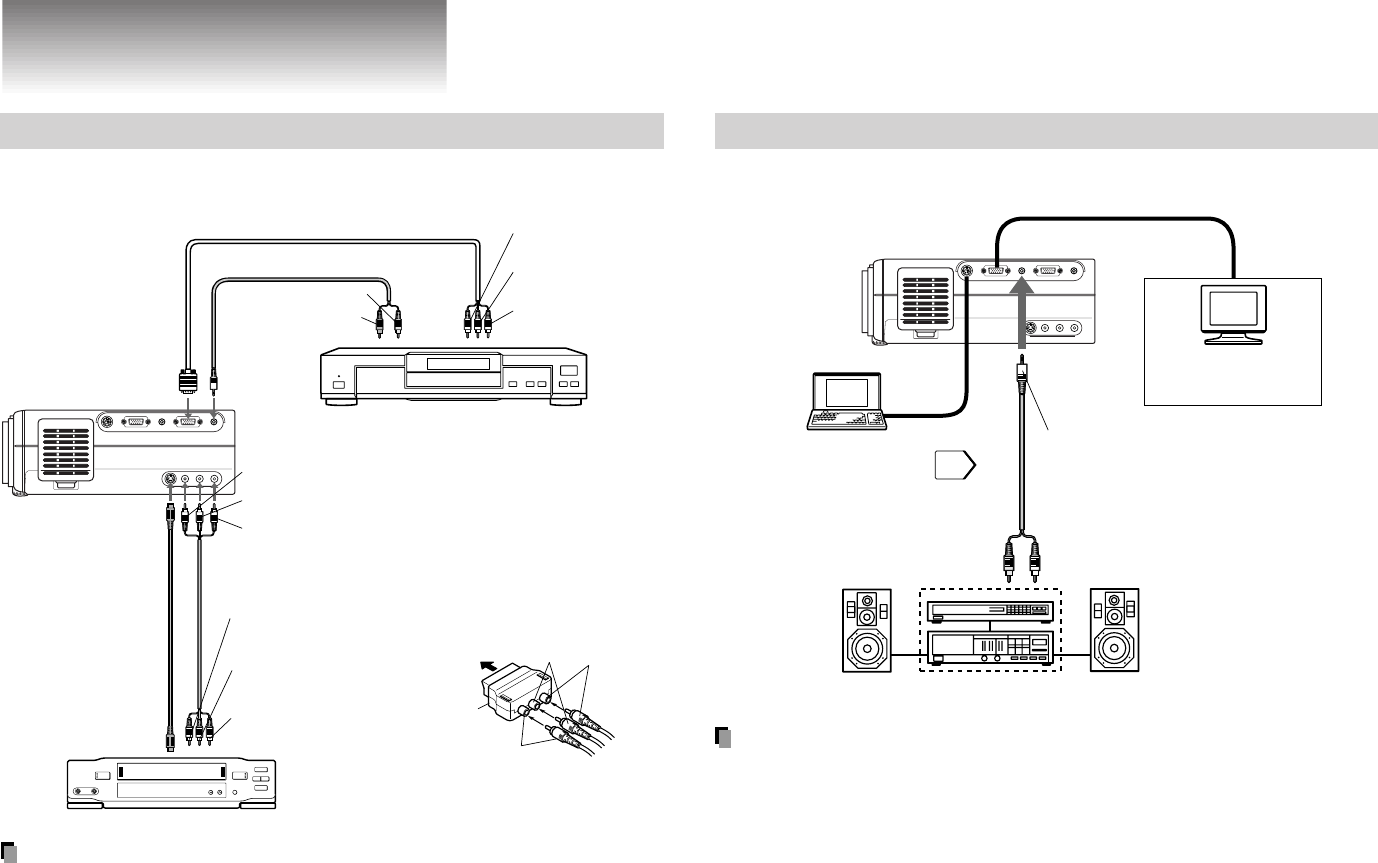
Connections
(Continued)
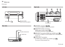
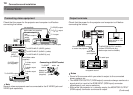
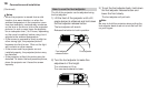
Connecting video equipment
Check that the power for the projector and computer is off before
connecting the cables.
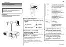
Output terminals
Check that the power for the projector and computer is off before
connecting the cables.
Notes
• Sound of the source which you select is output to the connected
stereo system, etc.
• The MONITOR OUTPUT (RGB output) connector always sends out a
signal which is input to the RGB INPUT (RGB input) connector
regardless of your source selection.
• Even while the projector is in standby mode, the MONITOR OUTPUT
(RGB output) connector continues its output.
Note
Several video equipments can be connected to the S-VIDEO jack and
VIDEO jack separately.
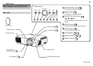
RS-232C
CONTROL
RGB AUDIO
MONITOR OUTPUT
RGB
S-VIDEO VIDEO
VIDEO INPUT
L - AUDIO -R
AUDIO
RGB INPUT
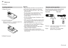
To VIDEO
INPUT
(S-VIDEO)
To S-VIDEO output
To Video output
(yellow)
To Audio output
(white)
To Audio output
(red)
yellow
white
red
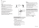
Adapter for
SCART socket
(supplied)
Audio/Video cable
(supplied)
S-VIDEO cable
(not supplied)
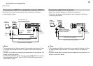
To RGB
INPUT
(RGB)
To RGB
INPUT
(AUDIO)
To P
R
(C
R
)
output
To P
B
(C
B
)
output
To Y output
Audio cable (not supplied)
(not supplied)
To audio output L
(white)
To audio output R
(red)
To VIDEO INPUT (VIDEO) (yellow)
To VIDEO INPUT (AUDIO L) (white)
To VIDEO INPUT (AUDIO R) (red)
To SCART
socket
Connecting to SCART socket
Video tape player
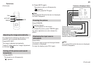
Video player with component video outputs
RS-232C
CONTROL
RGB AUDIO
MONITOR OUTPUT
RGB
S-VIDEO VIDEO
VIDEO INPUT
L - AUDIO -R
AUDIO
RGB INPUT
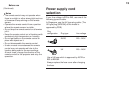
To MONITOR OUTPUT (AUDIO)
ø3.5mm STEREO mini plug
(Audio output level is constant.)
To audio input
Audio cable
(not supplied)
Connect a stereo system
for dynamic sound.
You can connect an
extra monitor to view
the picture.
You can connect a computer
to control the projector.
40