


19
Operations
18
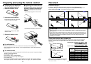
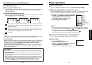
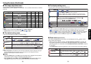
Connecting the power cord
1
Insert the power cord connector into the AC IN socket of the projector.
2
Insert the power cord plug into a wall or other power outlet.
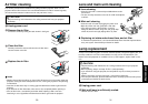
Removing the lens cover
Be sure to remove the lens cover when the power is
turned on. If it is left on, it could become deformed due
to heat.
■ Turning the power on
Press the ON/STANDBY
button.
The power turns on, and the
following 3 green indicators light:
ON, LAMP, and FAN. After a
moment, the start-up screen
appears.
CAUTION
• Do not look into the lens during operation. Doing so could damage your vision.
• Do not block the air intake or exhaust. Doing so could cause a fire due to internal
overheating.
• Do not place your hands, face, or other objects near the air exhaust. Doing so could
cause burns, deform/break the object.
Notes
• The start-up screen will disappear after a moment. You can dismiss the start-up screen
before this by performing any operation. You can also configure the start-up screen not to
appear via the Display setting menu
p.29
.
• The first time you use the projector after purchase, after the start-up screen disappears,
the Language menu is displayed
p.21
.
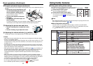
Turning the power on and off
When the power cord is plugged in, the following three
green indicators will come on for several seconds: ON,
TEMP, and LAMP. Next, the ON indicator will change to
orange, indicating standby mode.
(Do not perform any operations while the 3 green
indicators are lit.)
(Supplied) Power cord connector
Start-up screen
FAN
TEMP
LAMP
ON
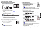
VOL.
+VOL.
-
ON / STANDBYINPUT
MENU
AUTO SET
AUTO
KEYSTONE
INPUT
ON/
STANDBY
RESIZE
OFF
CALL
AUTO
MUTE
RESIZE
FREEZE
SET
KEYSTONE
Control panel
Remote
Control
COMPUTER
(
Y/P
B
/P
R
)
S-VIDEOVIDEO
VIDEO
AUDIO
MONITOR
CONTROL
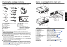
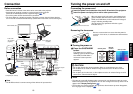
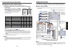
Before connection
• Read the owner’s manual of the device to be connected to the projector.
• Some types of computer cannot be used connected to this projector.
Check for an RGB output terminal, supported signal
p.36
, etc.
• Turn off the power of both devices before connection.
• The figure below is a sample connection. This does not mean that all of these devices
can or must be connected simultaneously. (Dotted lines mean items can be exchanged.)
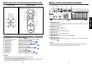
Note
• The AUDIO terminal is common among all the devices for input terminal.
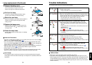
Connection
Computer
CRT monitor, etc.
To audio output
Audio cable
(for computer)
(supplied)
To RGB
output
Control cable
To RS-232C terminal
Computer (for control)
RGB cable
(supplied)
To Y/CB/CR
output
Green (Y)
Blue (CB),
Red (CR)
Yellow
(to video output)
To audio
output
White (L)
Red (R)
VCR
S-Video cable
(not supplied)
Video cable
(supplied)
To S-Video
output
To audio
output
White (L)
Red (R)
Monitor cable
Mini D-sub 15P-BNC
(not supplied)
Audio cable
(supplied)
DVD player
Conversion adapter
BNC-pin
(not supplied)
p.38