


TOSHIBA
G
7
APPLICATION GUIDELINE 8.0
* For additional assistance, please contact Toshiba Adjustable Speed Drive Marketing Dept. at (800) 872-2192
−
][10
][
][24
])[4(
*
V
VX
Or
mA
mAX
UL
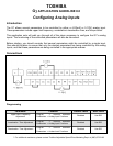
Torque Boost Adjustment
Program → Terminal Selection
Parameters → Analog Input Functions
Disabled Use RR*
* The VI/II input terminal can also be used.
Notes
For upper limit frequency the analog input will limit the upper limit frequency in the range 0 - UL[Hz]. If
the analog input receives 4[mA] or 0[V], the upper limit frequency will be 0[Hz]. If the analog input
receives 20[mA] or 10[V] the upper limit frequency will be set by Upper Limit in Program →
Fundamental Parameters →Frequency Settings. Intermediate inputs will result in a linear setting of
the upper limit frequency by the formula
Upper limit Frequency =
Where X is the input analog input in either mili-Amps or Volts. Note: accel/decel times are still
calculated with reference to Maximum Frequency.
Acceleration/Deceleration Time Adjustment - The analog input will determine a multiplier to the
Accel/Decel #1 parameters set in Program → Fundamental Parameters →Accel/Decel #1 Settings.
With a minimum input resulting in a multiplier of 1 and a maximum input resulting in a multiplier of 10
with intermediate inputs giving a linear multiplier between 1 and 10.
Torque Boost Adjustment – The analog input will determine the percentage of Torque Boost that the
drive will output at low speeds in a manner similar to that mentioned in the description of upper limit
frequency discussed above.