


CONTENTS
17
Connections and installation
(Continued)
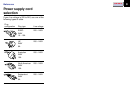
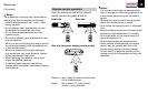
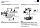
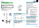
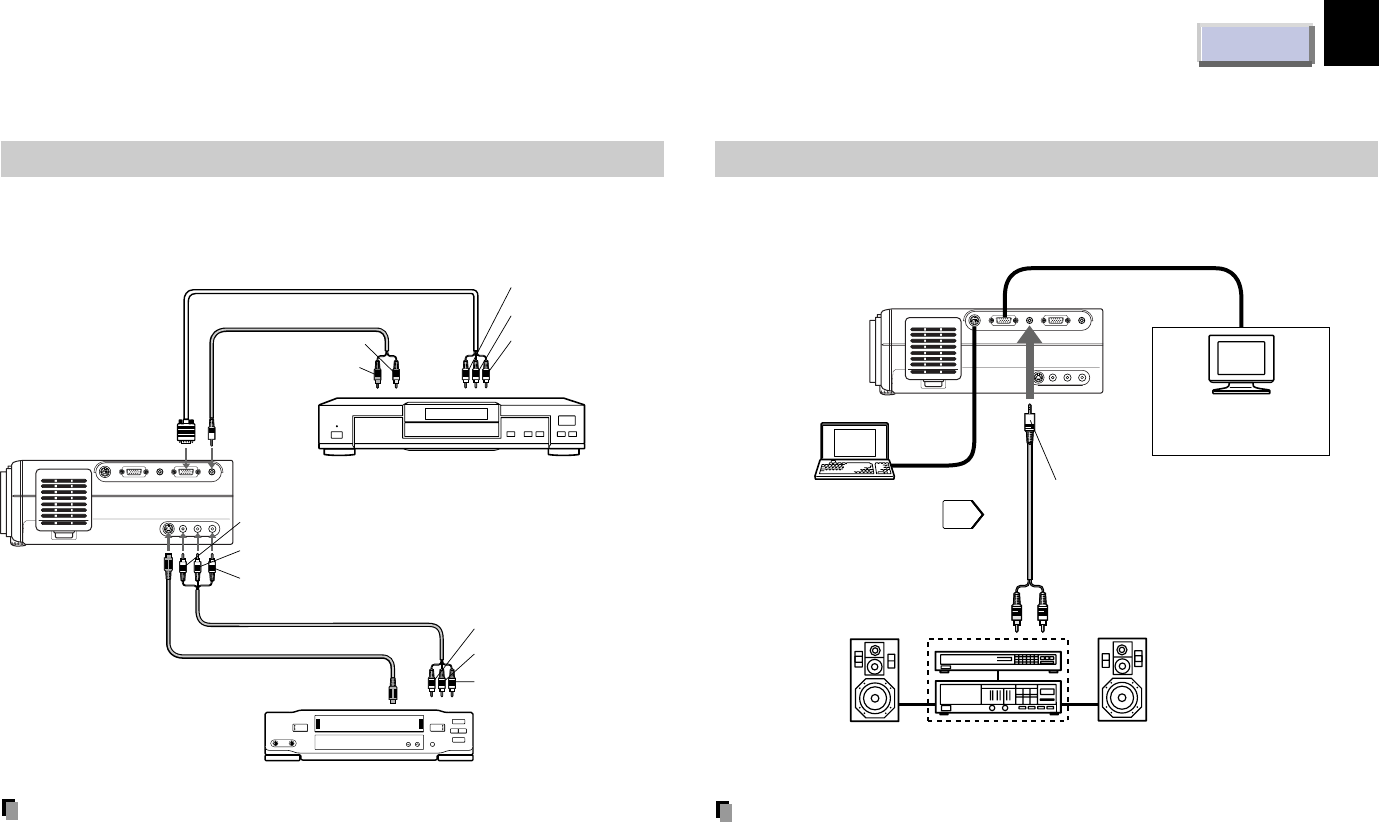
Connecting video equipment
Check that the power for the projector and computer is off before
connecting the cables.
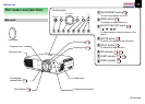
Output terminals
Check that the power for the projector and computer is off before
connecting the cables.
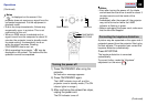
Notes
• Sound of the source which you select is output to the connected
stereo system, etc.
• The MONITOR OUTPUT connector always sends out a signal which
is input to the RGB INPUT connector regardless of your source
selection.
• Even while the projector is in standby mode, the MONITOR OUTPUT
connector continues its output.
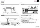
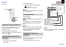
Note
Signal input to the S-VIDEO jack takes priority over that to the VIDEO
jack.
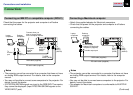
RS-232C
CONTROL
RGB AUDIO
MONITOR OUTPUT
RGB
S-VIDEO VIDEO
VIDEO INPUT
L - AUDIO -R
AUDIO
RGB INPUT
To MONITOR OUTPUT (AUDIO)
Ø3.5mm STEREO mini plug
(Audio output level is constant.)
To audio input
Audio cable
(not supplied)
Connect a stereo system
for dynamic sound.
You can connect an
extra monitor to view
the picture.
You can connect a computer
to control the projector.
49
RS-232C
CONTROL
RGB AUDIO
MONITOR OUTPUT
RGB
S-VIDEO VIDEO
VIDEO INPUT
L - AUDIO -R
AUDIO
RGB INPUT
To VIDEO
INPUT
(S-VIDEO)
To S-VIDEO output
To Video output (yellow)
To Audio output (white)
To Audio output (red)
Audio/Video cable (supplied)
S-VIDEO cable (not supplied)
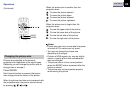
To RGB
INPUT
(RGB)
To RGB
INPUT
(AUDIO)
To C
R
(P
R
)
output
To C
B
(P
B
)
output
To Y output
Audio cable (not supplied)
(not supplied)
To audio output L
(white)
To audio output R
(red)
To VIDEO INPUT (VIDEO) (yellow)
To VIDEO INPUT (AUDIO L) (white)
To VIDEO INPUT (AUDIO R) (red)
Video tape player
Video player with color difference output