


E6581364
3
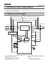
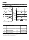
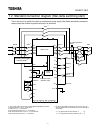
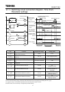
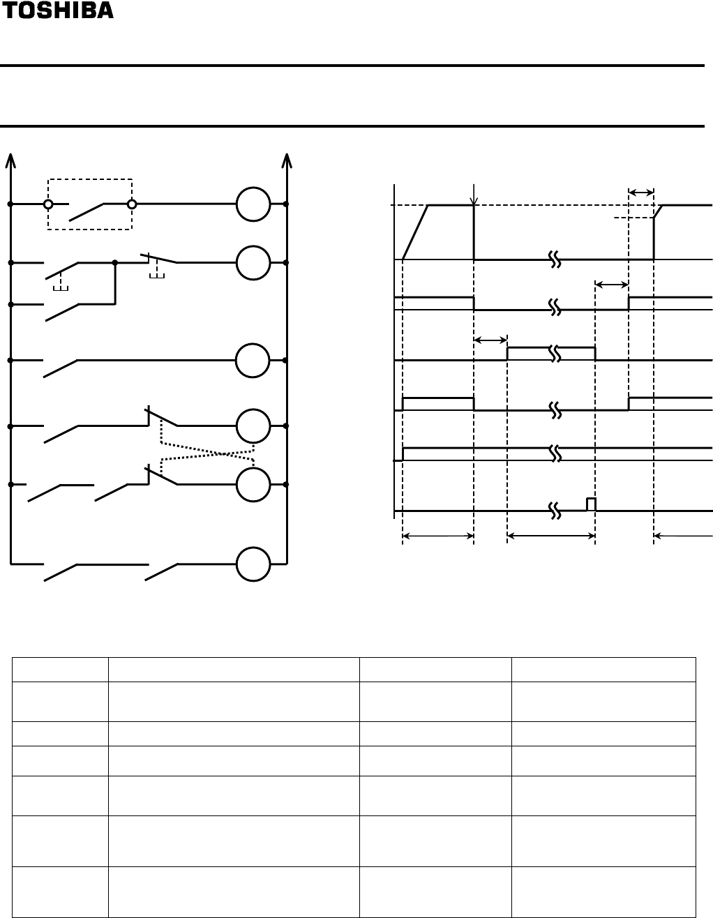
1.1.1. Switching circuit connection diagram, Time chart,
Parameter settings
Title Function Adjustment range Setting value
Output signal selection of commercial
power/inverter switching
0 to 3
1 (Automatic switching in case
of trip)
*3
Inverter side switching waiting time 0.1 to 10.0 seconds Different for each model
*3
Commercial power side switching waiting
time
0.37 to 10.0 seconds 0.62
*1
Input terminal selection #6 (S2) 0 to 135
20
(Emergency stop)
Output terminal selection #1 (OUT1) 0 to 119
46
(Commercial power/inverter
switching output 1)
Output terminal selection #2 (OUT2) 0 to 119
48
(Commercial power/inverter
switching output 2)
*1:Be careful about Items 5 and 7 in 1.3, “Precautions.”
*2:Due to internal processing timing, inverter-side wait time become 0.5 second longer than the setting value of
*3: and are included the operation time of the relay and the magnet contactor.
In almost all cases, it is not necessary to change these parameter settings.
Setting
frequency
Inverter-side switching wait
time
*2
Frequency after speed is
detected
Commercial power
switching wait time
S
p
eed detection time
Inverter run
Commercial power run
P24-OUT1(RY1)
for inverter
run
output
P24-OUT2(RY2)
for commercial
power run
output
Run signal
F-CC
Stand-by signal
ST-CC
ON
ON
ON
ON
ON
0Hz
Reset signal
RES-CC
Inverte
r
trip occurs
ON
Inverter run
Inverter protective
action signal
F L
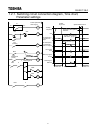
FLA FLC
FLX
X
F
OFFON
X
MC3
MC2
RY1
(
Inverter
)
X
MC3
MC1
MC2
RY2
(Commercial
p
ower
)
X