


E6581364
8
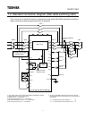
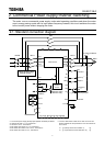
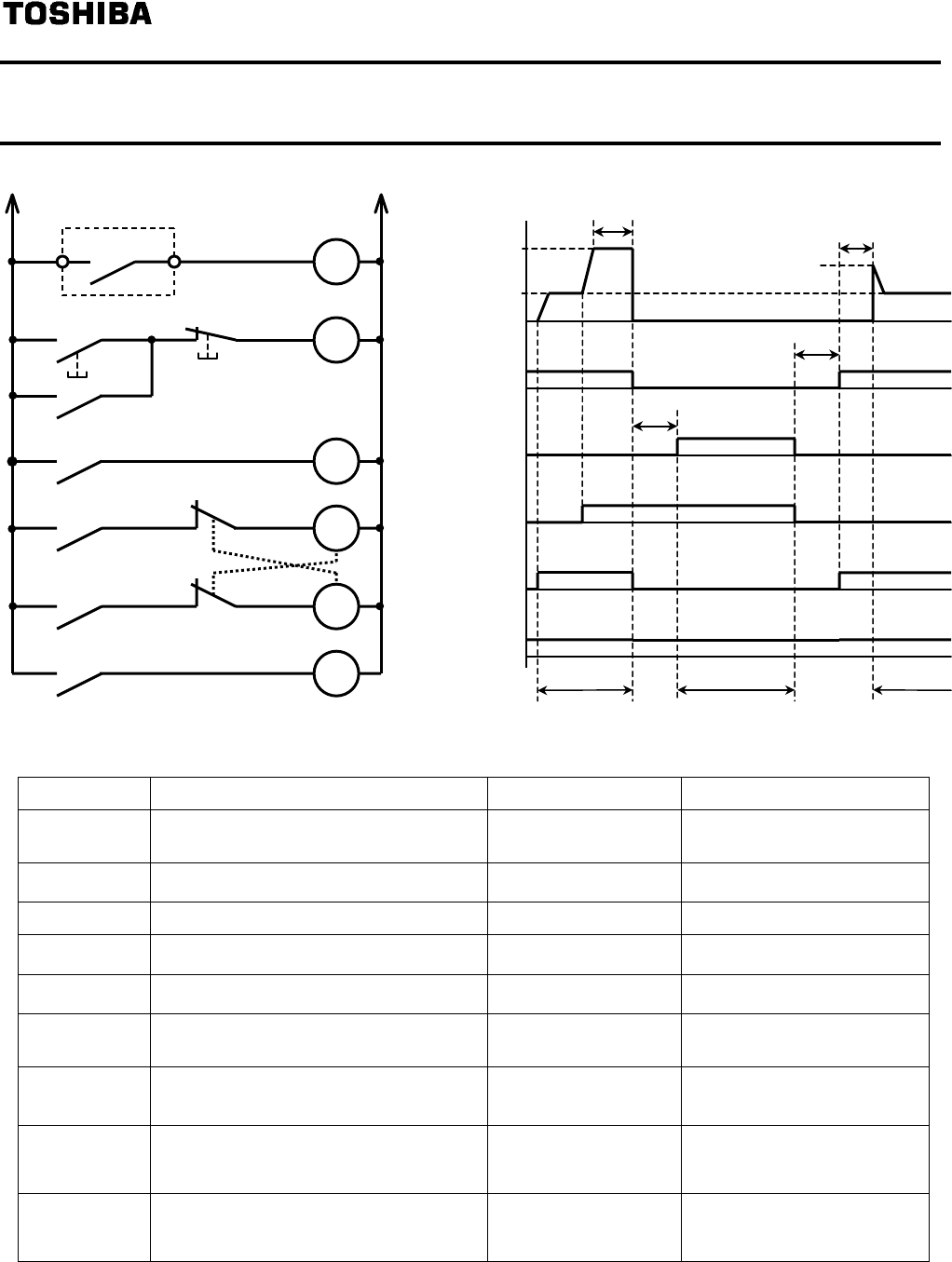
2.1.1. Switching circuit connection diagram, Time chart,
Parameter settings
Title Function Adjustment range Setting value
Output signal selection of commercial
power/inverter switching
0 to 3 2 or 3
Commercial power/inverter switching
frequency
0 to Power supply frequency
*3
Inverter side switching waiting time 0.1 to 10.0 seconds Different for each model
*3
Commercial power side switching waiting
time
0.37 to 10.0 seconds 0.62
Commercial power switching frequency
holding time
0.1 to 10.0 seconds 2.0
*1
Input terminal selection #6 (S2) 0 to 135
20
(Emergency stop)
Input terminal selection #7 (S3) 0 to 135
102
(Commercial power run
switching)
Output terminal selection #1 (OUT1) 0 to 119
46
(Commercial power/inverter
switching output 1)
Output terminal selection #2 (OUT2) 0 to 119
48
(Commercial power/inverter
switching output 2)
*1:Be careful about Items 5 and 7 in 2.2, “Precautions.”
*2:Due to internal processing timing, inverter-side wait time become 0.5 second longer than the setting value of
*3: and are included the operation time of the relay and the magnet contactor.
In almost all cases, it is not necessary to change these parameter settings.
Commercial power
switching frequency
Commercial power switching
frequency hold time
Commercial power
run switching signal
S3-CC
ON
ON
ON
ON
ON
ON
0Hz
ON
Inverter-side switching
wait time
*2
Frequency after speed is
detected
Commercial power
switching wait time
S
p
eed detection time
Inverter run
Commercial power run Inverter run
Setting frequency
P24-OUT1(RY1)
for inverter
run
output
P24-OUT2(RY2)
for commercial
power run
output
Run signal
F-CC
Stand-by signal
ST-CC
F L
FLA FLC
FLX
S3
MC3
MC1
F
(
Inverter
)
(Commercial
power)
S3
RY1(Inverter)
RY2(Commercial
p
ower
)
MC3
Inverter protective
action signal
MC2
MC2