


4 Replacement Procedures 4.11 Display Assembly
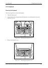
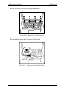
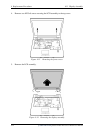
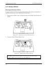
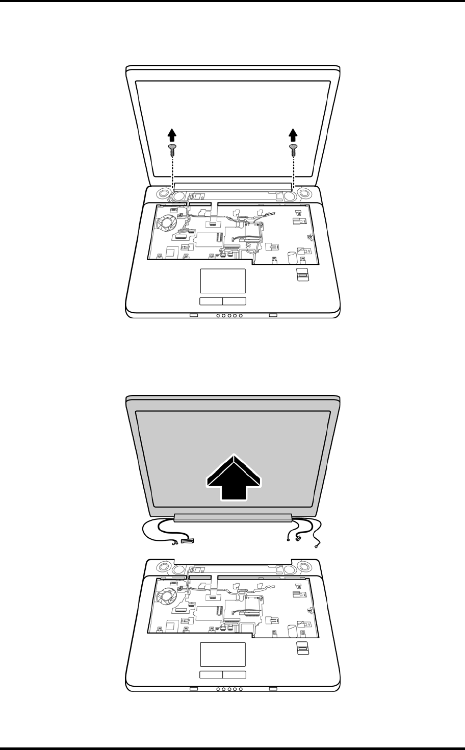
4. Remove two M2.5x8 screws securing the LCD assembly to the top cover.
Figure 4-33 Removing the front screws
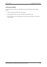
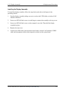
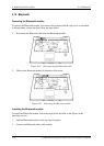
5. Remove the LCD assembly.
Figure 4-34 Removing the display assembly
4-32
[CONFIDENTIAL]
Satellite X200/ X205 Series Maintenance Manual