


TL-SF2226P+/TL-SL2226P+ Remote Smart Switch User Guide
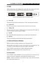
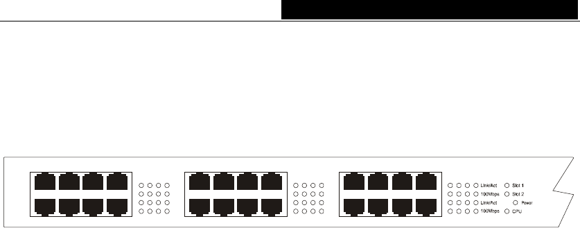
4.3 LED
LEDs, including Power LED, 100Mbps LED, Link/Act LED, Slot1, Slot2 and CPU LED,
can detect and indicate the state of the switch. More details are as follows.
17
19 21 23
18 20 22 24
9111315
10 12 14 16
1357
2
4
6
8
Figure 4-3 LED Indicators view of TL-SF2226P+ Switch
Power LED
The power LED will be solid red when power on, or else, check the power connection.
Link/Act LED
The LED is lit when there is a secure connection to a device at any of the ports.
100Mbps LED
When the normal ports connect a 100Mbps device, the corresponding LED is green, an
unlit LED indicates a connection speed of 10Mbps.
Slot LED
Slot1, Slot2 LED indicates that whether there is a module card in the module slot.
CPU LED
The CPU LED flashing means that the switch works in good condition.
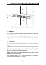
4.4 Optional Extension Modules
Before you install any modules, remember to turn off the power at first.
After you take out the board on the slot, put the module into the extension slot. The
TL-SF2226P+ can auto-identify the module and configure it automatically.
The TL-SF2226P+ can be used with TL-SM201 100M series modules.
Caution: Never install the modules without turning off the power.
4.5 Connection
The TL-SF2226P+ supports MDI/MDIX, so you can use every port as a normal port or an
uplink port. Each port is independent, which makes the connection very easy.
Caution: When the connection is ok, the Link/Act is light, or else, make sure the twist
pair is working and the power is on.
- 7 -