


05
Gigabit Unmanaged Switch
Introduction
LED Status Indication
PoE MAX
On (red)
The power of all the connected PoE ports is between
118W and 124W. No power may be supplied if
additional PDs are connected.
Flashing (red) The power of all the connected PoE ports is >=124W.
Off
The power of all the connected PoE ports is <118W, or
there is no PD connected to the corresponding port.
1000Mbps
On (green)
There is a 1000Mbps device connected to the
corresponding port.
O
ff
There is a 10/100Mbps device connected to the
corresponding port, or there is no device connected to
the corresponding port.
PoE Status
On (green)
There is a PoE PD connected to the port, which supply
power successfully.
Flashing (green)
The PoE power circuit may be in short or the power
current may be overloaded.
Off
No PD is connected to the corresponding port, or no
power is supplied according to the power limits of the
p
ort.
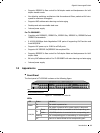
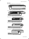
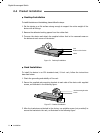
10/100/1000Mbps RJ45 Port and PoE Port
TL-SG1008PE switch is equipped with 8 10/100/1000Mbps Auto-Negotiation RJ45
ports and all of them support PoE function.
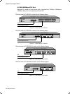
The 8 10/100/1000Mbps RJ45 ports are designed to connect to the device with
a bandwidth of 10Mbps, 100Mbps or 1000Mbps. Once the network devices are
connected to these 8 ports through the network cable, the switch will make them
plug and play according to the Auto-MDI/MDIX detection. The working status can be
indicated by the
Link/Act
LEDs and
1000Mbps LEDs
on the front panel.
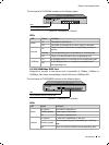
The 8 ports also support PoE function which integrates power and data onto
one Ethernet cable. Once the device you connect to the switch is identified, the
switch will supply power through the PoE port, and then you can use it as a
10/100/1000Mbps Auto-Negotiation RJ45 Ethernet port. The working status can be
indicated by the
PoE MAX
LED and
PoE Status LEDs
on the front panel.
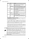
Note:
If all PoE PDs power consumption is >=124W, a priority* will be arranged among the
PoE ports like port 1 > port 2 > port 3 > port 4 > port 5 > port 6 > port 7 > port 8,
then the system will cut off the power of the lowest-priority port.
*Priority is to protect the system when the system power is overloaded. For example,
Port 1, 2, 4 and 7 is using 30; the system power is 120W in total. If there is an
additional PD inserted to Port 3 with 25W, and then the system will cut off the power
of Port 7 because of the overloaded power, this means Port 1, 2 and 4 will use 30W,
and Port 3 will use 25W, no power will be supplied to Port 7.
Make sure the PDs you connected to the Switch are compliant with IEEE802.3af/
IEEE802.3at standard.