


05
Gigabit Smart Switch
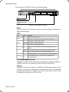
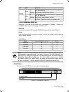
LED Status Indication
10/100/
1000Mbps
Green
On
A 1000Mbps device is connected to the corresponding
port, but no activity
Flashing Data is being transmitted or received
Yellow
On
A 10/100Mbps device is connected to the corresponding
port, but no activity
Flashing Data is being transmitted or received
Off No device is connected to the corresponding port
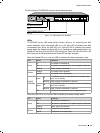
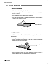
10/100/1000Mbps RJ45 Port
Designed to connect to the device with a bandwidth of 10Mbps, 100Mbps or
1000Mbps. Each has a corresponding 1000Mbps LED.
SFP Port
Designed to install the SFP module. TL-SG2452 features 4 individual SFP ports.
Reset
Press this button for five seconds or above to reset the software setting back to
factory default settings.
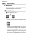
Port Feature
Model 10/100/1000Mbps RJ45 Port SFP Port
TL-SG2216 16 2
TL-SG2424 24 4
TL-SG2424P 24 4
TL-SG2452 48 4
Note:
For TL-SG2216/TL-SG2424/TL-SG2424P, when using the SFP port with a
100M module or a gigabit module, you need to log on to the GUI (Graphical User
Interface) of the Switch and congure its corresponding Speed and Duplex mode on
Switching
→
Port
→
Port Config page. For 100M module, please select 100MFD
while select 1000MFD for gigabit module. By default, the Speed and Duplex mode of
SFP port is 1000MFD. TL-SG2452 supports 1000M SFP module connection only.
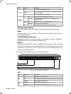
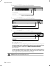
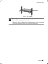
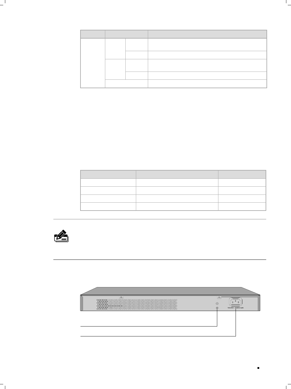
Rear Panel
The rear panel of TL-SG2216 is shown as the following figure.
Grounding Terminal
Power Socket
Rear Panel Figure 1-5
of
TL-SG2216
Introduction