


07
L2 Managed Switch
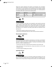
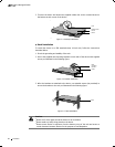
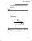
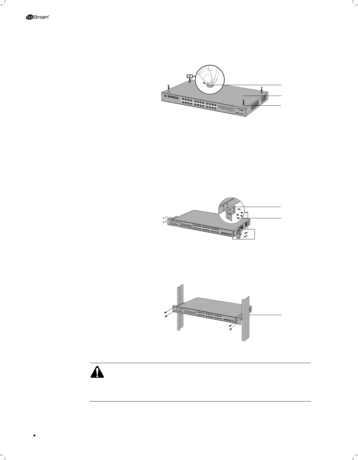
Turnover the device and attach the supplied rubber feet to the recessed areas on 3.
the bottom at each corner of the device.
TL-SG5428
Feet
Bottom of the
Device
Notch
Desktop InstallationFigure 2-1
Rack Installation
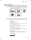
■
To install the device in an EIA standard-sized, 19-inch rack, follow the instructions
described below:
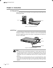
Check the grounding and stability of the rack.1.
Secure the supplied rack-mounting brackets to each side of the device with supplied 2.
screws, as illustrated in the following figure.
TL-SG5428
Rack-
mounting
Bracket
Screw
Bracket InstallationFigure 2-2
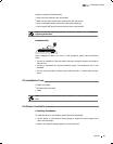
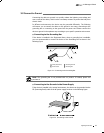
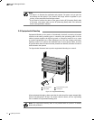
After the brackets are attached to the device, use suitable screws (not provided) to 3.
secure the brackets to the rack, as illustrated in the following figure.
TL-SG5428
Rack
Rack Installation Figure 2-3
Caution:
Please set 5~10cm gaps around the device for air circulation.
■
Please avoid any heavy thing placed on the device.
■
Please mount devices in sequence from the bottom to top of the rack and ensure a
■
certain clearance between devices for the purpose of heat dissipation.
Installation