


13
L2 Managed Switch
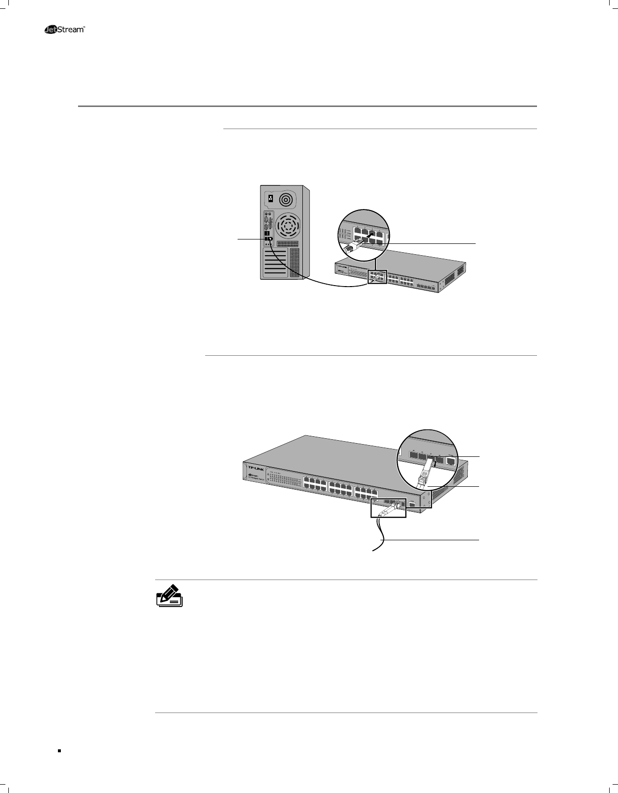
Connection
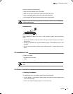
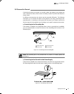
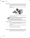
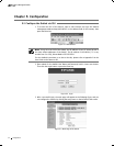
Connect the Ethernet ports of the Switch to the network devices by RJ45 cable as the
following figure shown.
TL-SG5428
RJ45 Cable
RJ45 Port
Connecting the RJ45 PortFigure 4-1
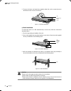
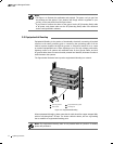
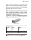
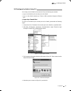
Connect the SFP port to a SFP module. For the switch, if an SFP transceiver (purchased
separately) is installed in a slot and has a valid link on the port, the associated RJ45
port will be disabled and cannot be used. Figure 4-2 demonstrates the connection of
SFP port to a SFP module.
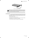
TL-SG5428
SFP Slot
Inserting the SFP ModuleFigure 4-2
Note:
A Combo port refers to two Ethernet interfaces in a device panel (normally one
■
is an SFP slot and the other is an RJ45 port). Inside the device there is only one
forwarding interface. Users can choose one to use depending on the actual network
requirements, but not two simultaneously. When one port is working, the other is
disabled.
For a Combo port, the SFP slot takes priority over its associated RJ45 port. When
■
the SFP slot and its associated RJ45 port are both connected, whatever the priority
of connection, the SFP port will always work normally while the RJ45 port will be
disabled.
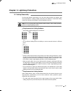
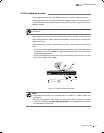
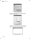
SFP Module
Optical Fiber