


4
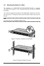
2.3 Mounting the SFP Module (for TL-SL1351 Only)
The front panel of the TL-SL1351 consists of a SFP module, which support The
Hot Plug- And- Draw. Should fixed the SFP into SFP pluggable when use the SFP
module. The switch could identify and configure the SFP module automatically.
2.4 Power on
TL-SL1210/TL-SL1117/TL-SL1226/TL-SL1351 Gigabit Switch is powered by AC
power supply. Powering on the Switch, it will automatically initialize and its LED
indicators should respond as follows:
1) All of the LED indicators will flash momentarily for one second, which
represents a resetting of the system.
2) The power LED indicator will remain ON.
Chapter 3 Identifying External Components
This Chapter describes the front panel, rear panel and LED indicators of the
Switch (here takes TL-SL1351 for example).
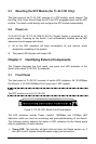
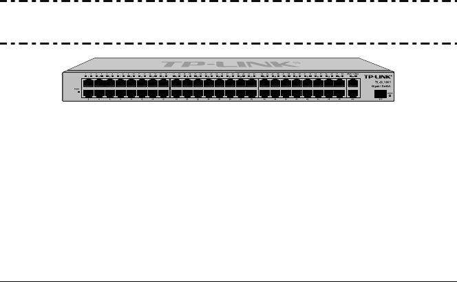
3.1 Front Panel
The front panel of TL-SL1351 consists of switch LED indicators, 48 10/100Mbps
RJ-45 ports, 2 10/100/1000Mbps RJ-45 ports and 1 SFP module.
Note:
The SFP module is only for TL-SL3151.
Figure 3-1 TL-SL1351 Switch Front Panel sketch
The LED indicators include Power, Link/Act, 1000Mbps and 100Mbps LED
indicators, which are used for monitoring and pre-troubleshooting of the Switch.
The following section explains the status of LED indicators for the Switch along
with an explanation of each indicator.
¾ Power LED: This indicator will light solid red when the Switch powers up. If
the LED is not lit, please check the power supply and connection.