


03
Smart Switch
Port Feature
Model 10/100Mbps RJ45 Port 10/100/1000Mbps RJ45 Port SFP Port
TL-SL2210 8 1 1
TL-SL2218 16 2 2(Combo)
TL-SL2428 24 4 2(Combo)
TL-SL2452 48 2 2
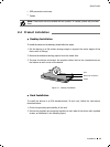
Reset(RESET)
With the switch powered on, press Reset button for five seconds to reset the
software setting to its factory default settings.
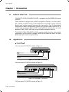
10/100Mbps RJ45 Port
Designed to connect to the device with a bandwidth of 10Mbps or 100Mbps. Each
has a corresponding 10/100M LED.
10/100/1000Mbps RJ45 Port
Designed to connect to the device with a bandwidth of 10Mbps, 100Mbps or
1000Mbps. Each has a corresponding 1000M LED.
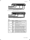
SFP Port
Designed to install the SFP module. TL-SL2218/TL-SL2428 features some SFP
transceiver slots that are shared with the associated RJ45 ports. The associated
two ports are referred as a "Combo" port, which means they cannot be used
simultaneously, otherwise only SFP por
t works. Meanwhile, the associated two ports
shar
e the same LED. For TL-SL2218, Port 17 shares the same LED with Port 17F and
Port 18 shares the same LED with Port 18F; for TL-SL2428 Port 27 shares the same
LED with Port 27F and Port 28 shares the same LED with Port 28F.
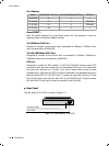
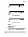
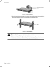
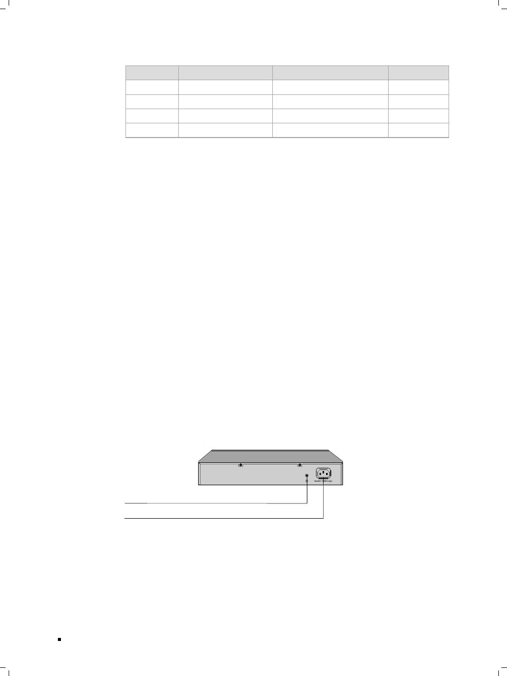
Rear Panel
The rear panel of TL-SL2210 is shown as Figure 1-5.
Power Socket
Grounding Terminal
Rear Panel of Figure 1-5 TL-SL2210
Introduction