


17
Smart Switch
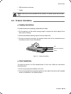
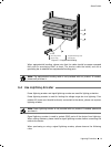
After completing the installation, please verify the following items:
There are 5~10cm of clearance around the sides of the device for ventilation and
the air flow is adequate.
The voltage of the power supply meets the requirement of the input voltage of the device.
The power socket, device and rack are well grounded.
The device is correctly connected to other network devices.
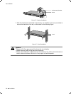
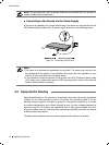
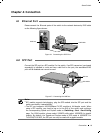
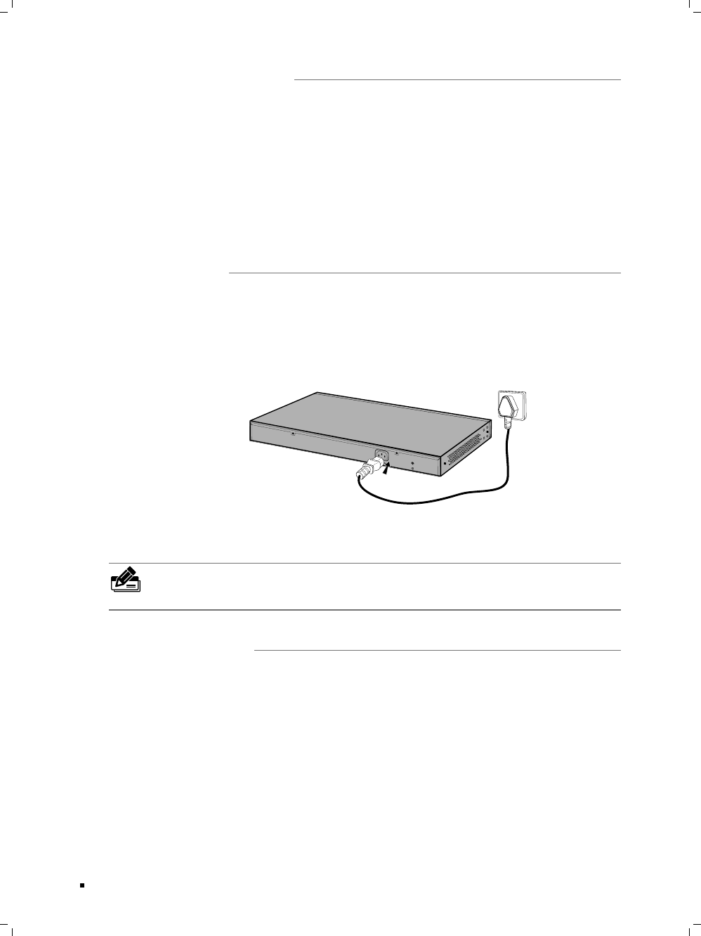
Plug in the negative connector of the provided power cord into the power socket of the
device, and the positive connector into a power outlet as the following figure shown.
Connecting to Power SupplyFigure 4-4
Note: The gure is to illustrate the application and principle. The power plug you get
from the package and the socket in your situation will comply with the regulation in
your country, so they may differ from the gure above.
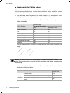
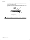
After the device is powered on, it begins the Power-On Self-Test. A series of tests run
automatically to ensure the device functions properly. During this time, its LED indica-
tors will respond as follows:
The Power LED lights on all the time.
After keeping off for several seconds, the LED indicators of all the ports will flash
momentarily and then turn off again after initialization.
The System LED indicator will flash, which represents a successful initialization.
Connection