


04
Smart Switch
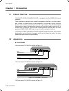
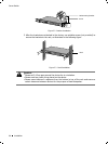
The rear panel of TL-SL2218 is shown as Figure 1-6.
Grounding Terminal
Power Socket
Rear Panel of Figure 1-6 TL-SL2218
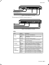
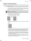
The rear panel of TL-SL2428 is shown as Figure 1-7.
Grounding Terminal
Power Socket
Rear Panel of Figure 1-7 TL-SL2428
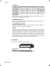
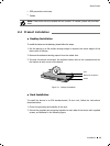
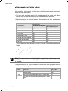
The rear panel of TL-SL2452 is shown as Figure 1-8.
Grounding Terminal
Power Socket
Rear Panel of Figure 1-8 TL-SL2452
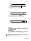
Power Socket
Connect the female connector of the power cord here, and the male connector to
the AC power outlet. Please make sure the voltage of the power supply meets the
requirement of the input voltage.
Grounding Terminal
The switch already comes with lightning protection mechanism. You can also ground
the switch through the PE (Protecting Earth) cable of AC cord or with Ground Cable.
For detailed information, please refer to Chapter 3 Lightning Protection.
Caution: Please use the provided power cord.
Introduction