


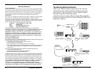
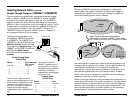

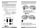

The Transition Networks pocket switch can be installed to provide one
10BASE-T switched port and one 100BASE-TX switched port.
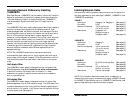
Auto-Negotiation
The 100BASE-TX standard includes automatic speed and duplex mode
sensing as part of the Auto-Negotiation function. When two Auto-
Negotiation devices with multiple capabilities are connected together,
they find their highest performance mode of operation based on a
priority`table. The Auto-Negotiation protocol contains a set of priorities
which result in the devices selecting their highest common set of
abilities. (The process happens out of band, with no loss of network
throughput.) Each 100BASE-TX station sends a burst of link integrity test
pulses, called a fast link pulse (FLP), generated automatically. If the
receiving switch is capable of 10BASE-T communication only, the FLPs
are ignored and the cable segment operates as 10BASE-T. If the switch
can support 100BASE-TX operation, the switch detects the FLPs, uses
the Auto-Negotiation algorithm and FLP data to determine the highest
possible cable segment speed and mode, and automatically places both
the station and the switch into 100BASE-TX mode.
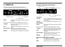
Transition Networks’ Pocket Switch
10
17
C
S
M
A
/
C
D
C
o
l
l
i
s
i
o
n
D
o
m
a
i
n
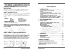
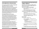
Existing 100 Mb/s
C
S
M
A
/
C
D
C
o
l
l
i
s
i
o
n
D
o
m
a
i
n
Existing 10 Mb/s
Install Transition Networks' Pocket Switch
To Connect Legacy Ethernet to Fast Ethernet
C
S
M
A
/
C
D
C
o
l
l
i
s
i
o
n
D
o
m
a
i
n
C
S
M
A
/
C
D
C
o
l
l
i
s
i
o
n
D
o
m
a
i
n
100 meters
10 Mb/s
100 meters
100 Mb/s
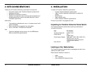
Installing Network Cable (continued)
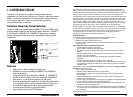
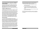
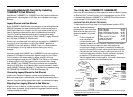
The 5-Segment Rule (10BASE-T)
The Ethernet 10BASE-T 5-segment rule defines a segment as the cable
connection between station interfaces. The transmission path between
any two terminal devices in the same collision domain can consist of
no more than five segments. Installing the Transition Networks’ pocket
switch in the network separates collision domains, so the 10BASE-T 5-
segment rule applies separately to each collision domain.
ASSIGNING SEGMENT NUMBERS
To assign segment numbers to cable connections:
1. Determine the network device separated from the Transition
Networks’ pocket switch by the greatest number of segments.
2. Define a segment path between that network device and the
Transition Networks’ pocket switch by labeling the cable
connection to the Transition Networks’ pocket switch “segment
1” and numbering each segment in the path to the terminal up
to “segment n” (n = total number of segments ≤ 5).
3. Verify that no segment path in the collision domain contains
more than n ≤ 5 segments.
4. Repeat steps 1-3 for next collision domain.
hub
hub
hub
hub
3
4
5
2
1
hub
hub
hub
hub
3
4
5
2
Collision Domain
1
Collision Domain