


Installing Network Cable (continued)
Connecting Fiber Cable to TX/RX Connectors
(100BASE-FX)
Effective cable distances are determined by ambient RF noise and by
signal loss in the cable. Since fiber has a low signal loss/meter and is
invulnerable to RF noise, fiber can be used to extend distances.
OPTICAL POWER LOSS BUDGET
An 11dB loss budget, as measured by a fiber optic power meter, is
allowed per link. A typical performance rating for standard grade fiber
operating at 1350 nm is approximately 1dB-2dB loss per 1000 meters of
cable. Approximately 0.5dB-2.0dB loss per connection point is typical,
depending on how well the connection has been made.
FAST ETHERNET COLLISION DOMAIN
NOTE: Installing full-duplex fiber cable avoids collision domain
considerations and extends distances up to 2000 meters.
A Fast Ethernet collision domain can have ONLY ONE CLASS I repeater
OR TWO CLASS II repeaters.
Refer to the 512-Bit Rule (page18) regarding Fast Ethernet collision
domains before installing half-duplex 100BASE-FX cable (≤ 415 meters).
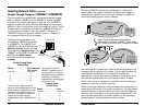
INSTALLING CABLE
To install 100BASE-FX cable:
1. Locate or build 100BASE-FX cables with the following
characteristics:
• 803.2u compliant (See page 28)
• male ST transmit and receive fiber connectors installed at
both cable ends.
2. At Transition Networks’ pocket switch, connect transmit cable
connector at one end of fiber cable to ST connector marked
with an “outbound” arrow; connect receive cable connector to
ST connector marked with an “inbound” arrow.
3. Connect cable installed at transmit (TX) connector of Transition
Networks’ pocket switch at receive (RX) connector of device at
other end; connect cable installed at receive (RX) connector at
transmit (TX) connector of device at other end of fiber cable.
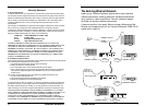
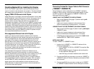
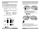
When installed in a legacy 10BASE-T Ethernet network, the Transition
Networks’ pocket switch segments network traffic on the original
10Mb/s Ethernet collision domain into two distinct 10Mb/s Ethernet
collision domains.
Ideally, the system administrator defines collision domain segments so
that most traffic on each segment is local to the segment.
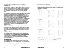
MAC Address Table
The dynamic internal routing table of the Transition Networks’ pocket
switch provides self learning capabilities for up to 8192 MAC addresses
of incoming and outgoing packets. Once a network node address is
stored in the MAC address table, data packets addressed to that node
are sent directly. Packets whose destination address is on the same
CSMA/CD collision domain as the packet source address are discarded
by the pocket switch. NOTE: The MAC address table is volatile and
disappears when the pocket switch is powered off or reset.
Transition Networks’ Pocket Switch
6
21
C
S
M
A
/
C
D
C
o
l
l
i
s
i
o
n
D
o
m
a
i
n
C
S
M
A
/
C
D
C
o
l
l
i
s
i
o
n
D
o
m
a
i
n
C
S
M
A
/
C
D
C
o
l
l
i
s
i
o
n
D
o
m
a
i
n
100 meters
10 Mb/s
100 meters
10 Mb/s
Install Transition Networks' Pocket Switch
To Divide Repeater Stack Collision Domain
100 meters
Existing 10 Mb/s Network