


2
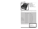
SBFTF10xx-12x
24-hour Technical Support: 1-800-260-1312 -- International: 00-1-952-941-7600
* Typical maximum cable distance. Actual distance is dependent upon the
physical characteristics of the network. (TX) = transmit (RX) = receive
** SBFTF1029-120 and -121 are intended to be installed in the same network
where one is the local converter and the other is the remote converter.
*** SBFTF1029-122 and -123 are intended to be installed in the same network
where one is the local converter and the other is the remote converter.
The chassis version of the media converter is CBFTF10xx-12x. For more
information, see the CBFTF10xx-12x user’s guide on-line at: www.transition.com.
Installation
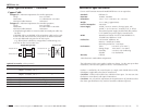
Copper and Fiber Ports
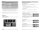
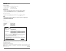
The figure below illustrates the locations of the five (5) twisted-pair copper ports
and the one (1) fiber port.
Part Number Copper - five (5) ports
10Base-T/100Base-TX
Fiber-Optic - one (1) port
Single Fiber
SBFTF1029-120 RJ-45
100 m (328 ft)*
SC, 1310 nm (TX)/1550 nm (RX)
single mode, 20 km (12.4 miles
SBFTF1029-121 RJ-45
100 m (328 ft)*
SC, 1550 nm (TX)/1310 nm (RX)
single mode, 20 km (12.4 miles)*
SBFTF1029-122 RJ-45
100 m (328 ft)*
SC, 1310 nm (TX)/1550 nm (RX)
single mode, 40 km (24.8 miles)*
SBFTF1029-123 RJ-45
100 m (328 ft)*
SC, 1550 nm (TX)/1310 nm (RX)
single mode, 40 km (24.8 miles)*
10/100TX
10/100TX 10/100TX
100Base-FX
FD
LACT
PWR
Twisted-Pair
Port 1 (TP1)
Twisted-Pair
Port 4 (TP4)
Twisted-Pair
Port 5 (TP5)
Fiber Port 1
(F1)
10/100TX 10/100TX
Twisted-Pair
Port 2 (TP2)
Twisted-Pair
Port 3 (TP3)
Installation -- Continued
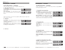
Set the Dip Switches
The dip switches are located on the side of the media converter. Use a small,
flat-blade screwdriver or a similar device to set each dip switch.
“SW1” switches 1 - 6
Dip switches 1, 2, and 3 apply only to twisted-pair copper port 1 (TP1).
Dip switch 4 applies to fiber port 1 (F1).
Dip switch 5 applies to all twisted-pair copper ports (TP1, TP2, TP3, TP4, TP5).
Dip switch 6 is not in use.
“Config. Switches” 1 - 4
Dip switches 1, 2, 3, and 4 apply only to twisted-pair copper port 2 (TP2).
NOTE: Switches 1, 2, and 3 apply only to twisted-pair copper port 1 (TP1).
techsupport@transition.com -- Click the “Transition Now” link for a live Web chat.
3
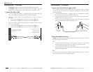
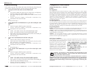
1. Twisted-Pair Auto-Negotiation
Up (Enabled) - The media converter “advertises”
ALL rate and mode capabilities to the network:
• 100Mb/s full-duplex • 100Mb/s half-duplex,
• 10Mb/s full-duplex • 10Mb/s half-duplex.
Down (Disabled) - The bridging media converter
does not “advertise” the rate and mode capabilities
to the network. Switches 2 and 3 are then used to
set the twisted-pair rate and mode.
2. Twisted-Pair Rate
Up (100Base-TX) - Sets the twisted-pair rate to
100Base-TX.
Down (10Base-T) - Sets the twisted-pair rate to
10Base-T.
3. Twisted-Pair Mode
Up (Full-Duplex) - The twisted-pair cable
distances are constrained by the cable
requirements (see pages 1 and 2).
Down (Half-Duplex): - The twisted-pair cable
distances are constrained by the 512-Bit Rule (see
page 9).
DOWN
1
UP
Twisted-Pair Auto-Negotiation ON
Twisted-Pair Auto-Negotiation OFF
Twisted-pair 100Base-TX
Twisted-pair 10Base-T
DOWN
UP
2
Twisted-pair Full-Duplex
Twisted-pair Half-Duplex
DOWN
UP
3