


SMART CAT5 SWITCH – 108/116
1
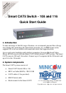
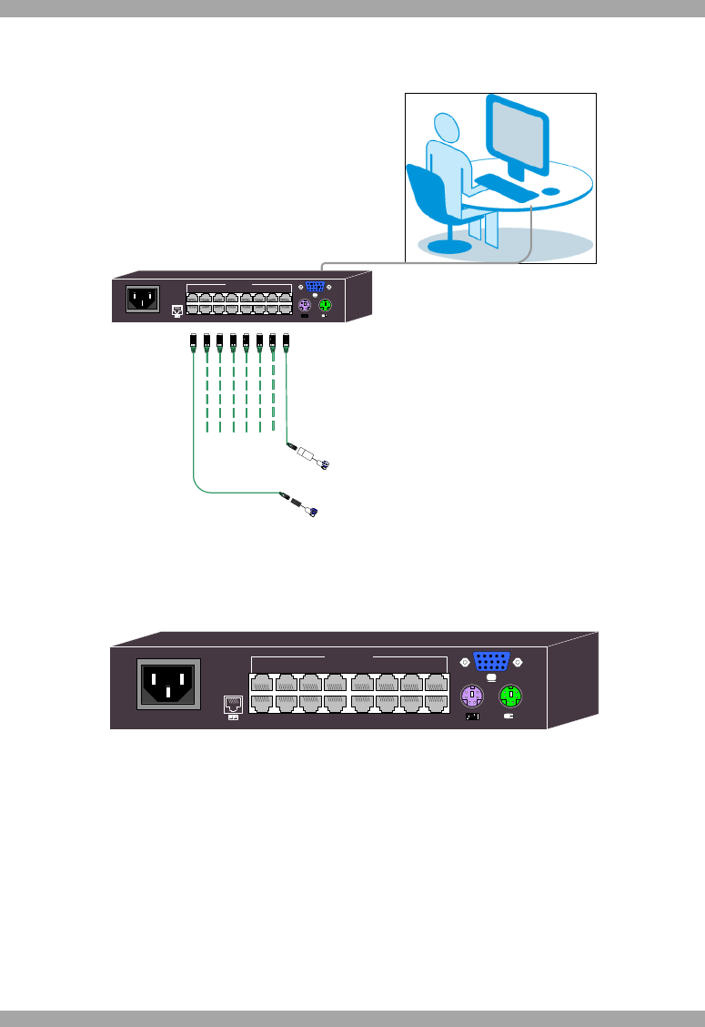
3. The Smart CAT5 system configuration
Figure 1 illustrates the basic configuration of the Smart CAT5 system.
Figure 1 Smart CAT5 system configuration
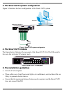
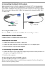
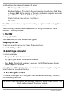
4. The Smart CAT5 models
The figure below illustrates the rear panel of the Smart CAT5 116. The 108 model is
the same but with only 8 Computer ports.
Figure 2 Smart CAT5 116 rear panel
5. Pre-installation guidelines
Switch off all computers
Place cables away from fluorescent lights, air conditioners, and machines that are
likely to generate electrical noise
Ensure that the maximum distance between each computer and the Smart CAT5,
does not exceed 10m/33ft
Workstation
To servers
M
I
N
I
C
O
M
POWER
100-240 VAC 50/60 Hz
1 2 3 4 5 6 7 8
10 11 12 13 14 15 169
COMPUTER
www.minicom.com
SMART CAT5 SWITCH 116
RoC/RICCs
to servers
POWER
100-240 VAC 50/60 Hz
1 2 3 4 5 6 7 8
10 11 12 13 14 15 169
COMPUTER
www.minicom.com